I’ve always been sort of a time nut, but that’s pretty closely related to frequency. The ARRL helps to sponsor a periodic Frequency Measurement Test, usually held in April and November. A good friend of mine, John WA1ABI, always participates and usually has outstanding accuracy. I’ve always been fascinated by that, so I went looking for some surplus gear.
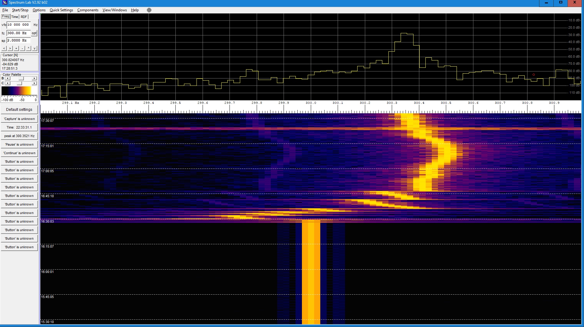
My plan was to us a milliHertz resolution frequency synthesizer to generate a carrier of known frequency that was manually adjusted to be within a few hundred Hertz below the unknown signal. A RX in AM mode would produce a heterodyne audio beat note equal to the frequency difference. Add the audio frequency to the known frequency and the unknown will be revealed.
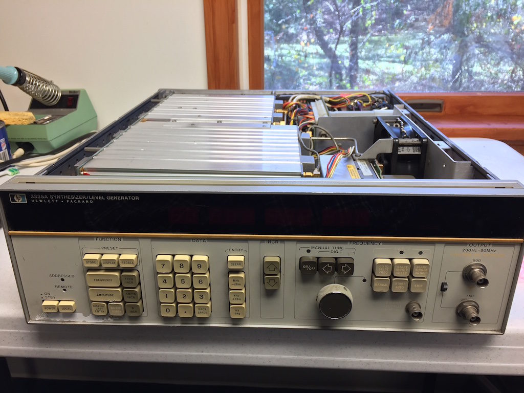
I put my sites on a HP 3335A signal generator. This is a massive beast that is about 40 years old (would have been new when I started my first engineering job in the late 1970s). They are fairly common on eBay, and can be found in various states of disrepair. I happened to locate one locally from someone who had worked on closing a capacitor factory in Massachusetts. The good news was it was inexpensive. The bad news it was sort of working and absolutely filthy.
After several hours of scrubbing the covers, they now are no longer sticky to the touch and dirty, but they show 40 years worth of wear and tear. The unit powers up and generates a fantastically stable/repeatable signal (the internal 10 MHz source, once warmed up for an hour, is within 44 milliHertz of spot on — that’s 4.4 parts per BILLION). It is pretty amazing to be able to change any of the 10 digits by one and see that exact change show up in the output.
But there is a significant problem. The unit randomly resets itself every 30 – 300 seconds. At that point the frequency is reset to 1.0 MHz, and the output level drops down below -80 dBm. The reference oscillator remains running, and within a fraction of a second of entering the frequency and amplitude via the keypad, it is up and running again.
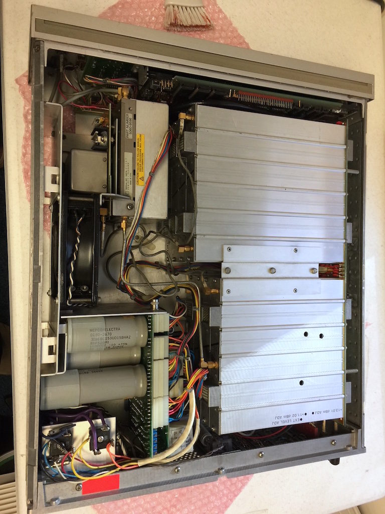
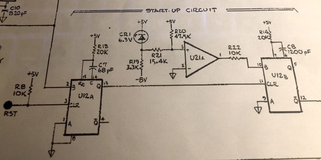
After going through the service manual and schematics, it appears the only reason this would happen is if there were a voltage issue with the internal 5 volt supply. That could cause the 6800 CPU to reset. The 3335A never really powers off fully. The unregulated supplies are always on as long as the power cord is plugged in. It is highly likely that 40 years of this has fried the large power supply caps, and that would make the 5 volt supply unstable. We shall see!