The Annobon Island DXpedition has been racking up QSOs. I finally got a chance to listen to their 160 meter signal tonight and it’s outstanding here in RI. Haven’t broken through the pileup yet.
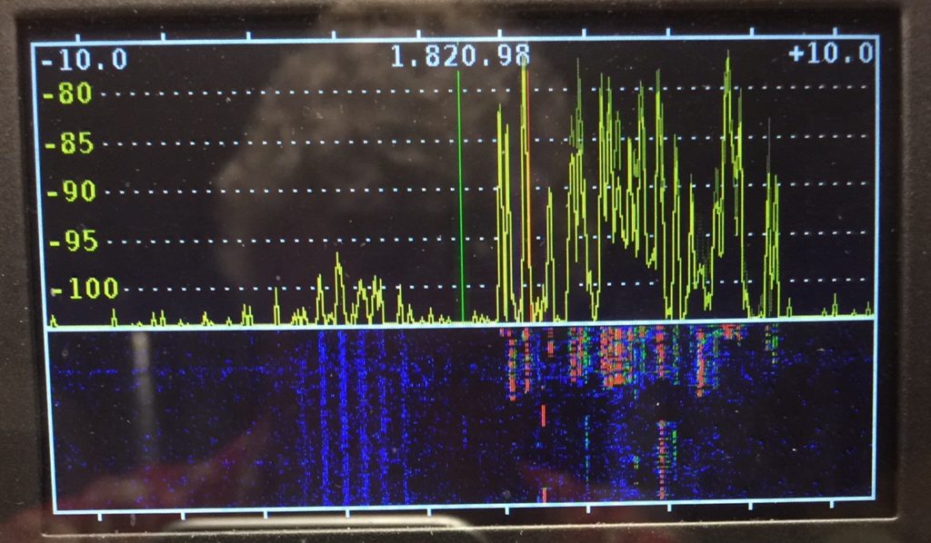
The Annobon Island DXpedition has been racking up QSOs. I finally got a chance to listen to their 160 meter signal tonight and it’s outstanding here in RI. Haven’t broken through the pileup yet.
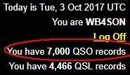
While I am sure I’ve had many more QSOs (I’ve got many old written logbooks from 1970-2000), I didn’t start using LotW until I got back on the air in February of 2011.
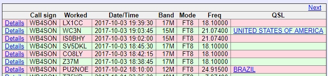
Today I entered my 7,000th QSO into LotW. It was with Mill, LX1CC, in Luxembourg. No special prize, and I don’t know why 7,000 feels different from 6,999 or 7,001, but it seemed worth marking.
A massive solar flare struck the earth today, a X-class 9.3. This is the largest flare of Solar Cycle 24 by far. It does have an Earth-directed CME that will be following on the heels of an earlier M-class flare/CME.
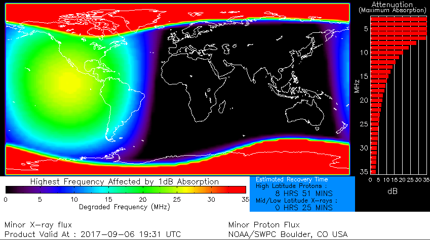
Image at peak absorption near the US about 7 hours later
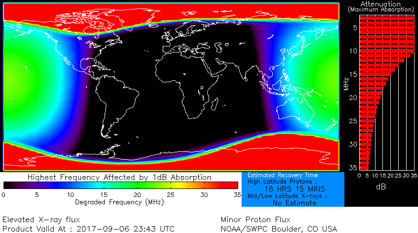
The absorption at the time of this posting is worse:
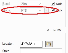
Version 6.3.0.613 (Dec 2016) of HRD predates the WSJT-X “FT8” mode. If you use the latest version of JTAlert (2.10.1), it has added back in HRD version 6.3+ logging support (but only temporarily, according to the author). That’s great, but you need to make a change to the HRD Logging program to support FT8. If you don’t it will log the contact as “FM” (the closest thing alphabetically).
Open the logging program and select “Tools/Configure/Modes”. Click “ADD” on the “Modes Editor” window that pops up, then populate Mode/ADIF/Comment for FT8 as follows: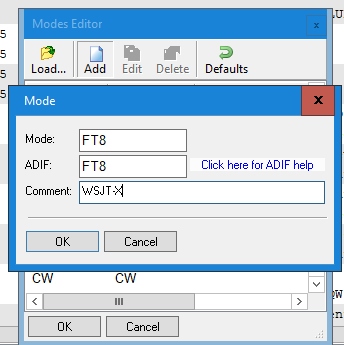
After making that change, FT8 will show up at the end of the list of available modes, and it will automatically be selected when you use JTAlert to log a contact.
NOTE: LotW doesn’t support FT8 yet, explicitly, converting it to a generic “Digital” mode. The ADIF.org group has added FT8 to version 3.0.6 of the spec, so the change in LotW will happen soon.
I’ve been bouncing between my Windows PC and a Macbook Pro as I am writing the code for the Feather NTP Clock. (Gotta love BitBucket and TortoiseHG which provide me with the latest source code wherever I am).
While it isn’t unique to the Adafruit Feather, I’ve been having frequent OS X Kernel Panics — the Mac equivalent of a Blue Screen of Death — when using the Arduino IDE with the Feather connected via USB. The Macbook always recovers but the reboot process is about a minute long.
There is lots of online stuff, mostly rumors of fixes like loading signed drivers for the Chinese CH340 USB chip, which isn’t used by the Feather at all. Sadly, none of the online suggestions works.
What DOES work, is using a USB Hub. In my case it was a DLINK Powered USB 2.0 hub, but I suspect that any hub would be adequate, because the Powerbook USB connection is no longer direct to the Arduino device.
NOTE: Using a hub will certainly change the OS X detected port, so make sure to get the correct port selected in the IDE.
While my obsession with accurate time continues, these days my obsession with avoiding the hassle of resetting clocks on DST/STD changeover and power failures grows.
My original NTP Clock, based on the Raspberry Pi worked just fine, but it really didn’t like power failures, which sometime trashed the SD card, plus it was about $75 or so per clock.
The Adafruit Feather M0 WiFi board has caught my attention. It’s darned tiny, and very power stingy. Add a FeatherWing OLED board, and you’ve got the hardware required for a tiny (2.1″x0.8″) NTP Clock that costs about $50.
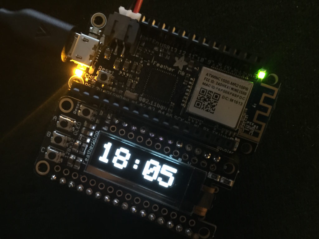
Adafruit Feather M0 WiFi with FeatherWing OLED Display
 After messing with HRD & QSO Relay, I determined that inability to support FT8 with older HRD versions was a show stopper for me.
I decided to use ACL, which was fully supporting FT8 and simply gather my digital FT8/JT9/JT65 contacts in that log until such time that LotW accepts the FT8 mode.
My first snag was in creating a ADIF file for export from HRD. In the default display order, where newer contacts appear at the top of the screen, the order of the ADIF file is reversed (leading to the higher numerical entry number being the oldest log entry. So I simply reversed the display order (clicking on the date column), and exported that file.
Importing that into ACL went fine, but ACL doesn’t keep track of any confirmation data during that sort of import. That meant that every FT8/JT9/JT65 station was needed. The fix for that situation was to download my entire LotW log, a process that took about 15 minutes to complete. That corrected things, so I was able to scan the log and now had proper “need” data shown in JTAlert
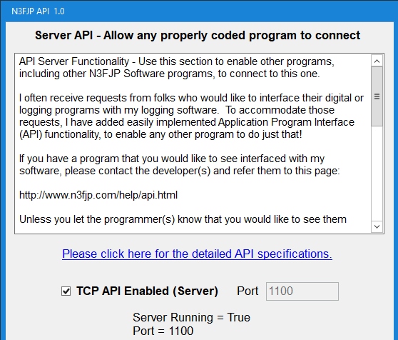
Finally, so that JTAlert can put log entries into ACL, the Settings/Application Program Interface Enabled Checkbox must be set
I see a lot of activity on 20 meters using the new FT8 mode (14.074.000), so I figured I would bite the bullet and update. The latest WSJT-X release candidate requires an update to JTAlert, which I was avoiding since it no longer works with HRD version 6+ logging.
There is a utility out there called “QSO Relay” that acts as a go-between from JTAlert and HRD. It works fine, but there is a deeper issue. Older versions of the HRD logging program such as mine (6.3.0.613) don’t know what the mode “FT8” is. The QSO Relay utility will populate the HRD log with the mode set to FT8, but if you touch the log entry at all, perhaps adding a comment, or just doing a lookup to populate the remaining contact info (like name, city, etc.), the Mode is forced to “FM” — I guess it is the closest thing HRD can find to “FT8”. (Why HRD needs to modify that field is beyond me.)
So that is a show stopper in terms of using HRD. Even with everything else working correctly, without an update to HRD to a version that understands FT8, things are not going to work for contact confirmation.
Another show stopper is that LotW does NOT recognize FT8 as a valid mode (like JT65, or JT9), so it is not possible to upload these to LotW, without changing the mode to something like “DIGITAL” using the TQSL ADIF Mode Overlay.
Anyway, thanks to W5LE for being my first FT8 QSO. I’ll manually upload it to LotW as soon as that mode is supported.
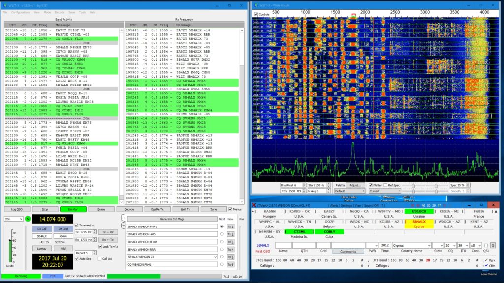
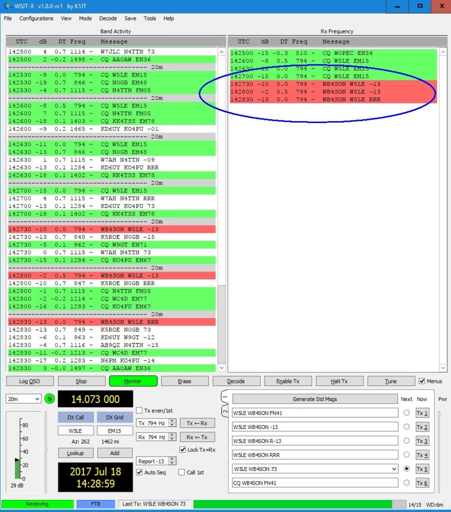 Ignore the “14.073 000” shown above — there is a slight polling delay when going from transmit to receive, the display above was still showing my transmit VFO setting, and had not updated to the usual 14.074 000 receive setting.
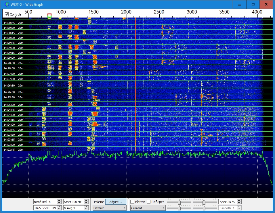
Waterfall showing FT8 exchanges. W5LE QSO is in the middle (you can see the shorter TX bars)
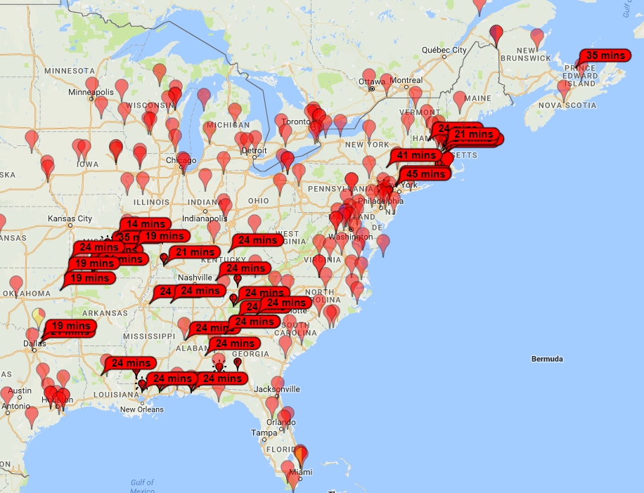
The JT65 segment of 6-meters was white hot today. Even heard Joe Taylor (K1JT). Map below shows stations that heard my signals around 21:00 UTC today.
Last night I was NCS for my club’s HF net. Right after our net cleared, K2C, a station in RI started calling CQ for the 13 Colony Special Event, and I picked him up, along with several of the other net members. At that point, I figured it was prime time for 40 and 80 meters up and down the East Coast, so I went looking for some others. About 45 minutes later I had worked 11 of the 13 stations. It took quite awhile to find a PA station (I thought that was unusual), and I was still missing K2L in SC before I turned in for the night. This morning after my club breakfast, I found K2L on 40 meter CW as well as WM3PEN, the Liberty Bell Bonus station, completing a clean sweep of all original colonies plus a bonus station:
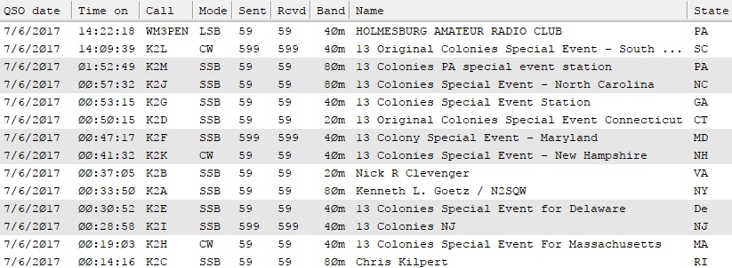
My thanks to all the operators of stations K2A to K2L for making this a fun event.