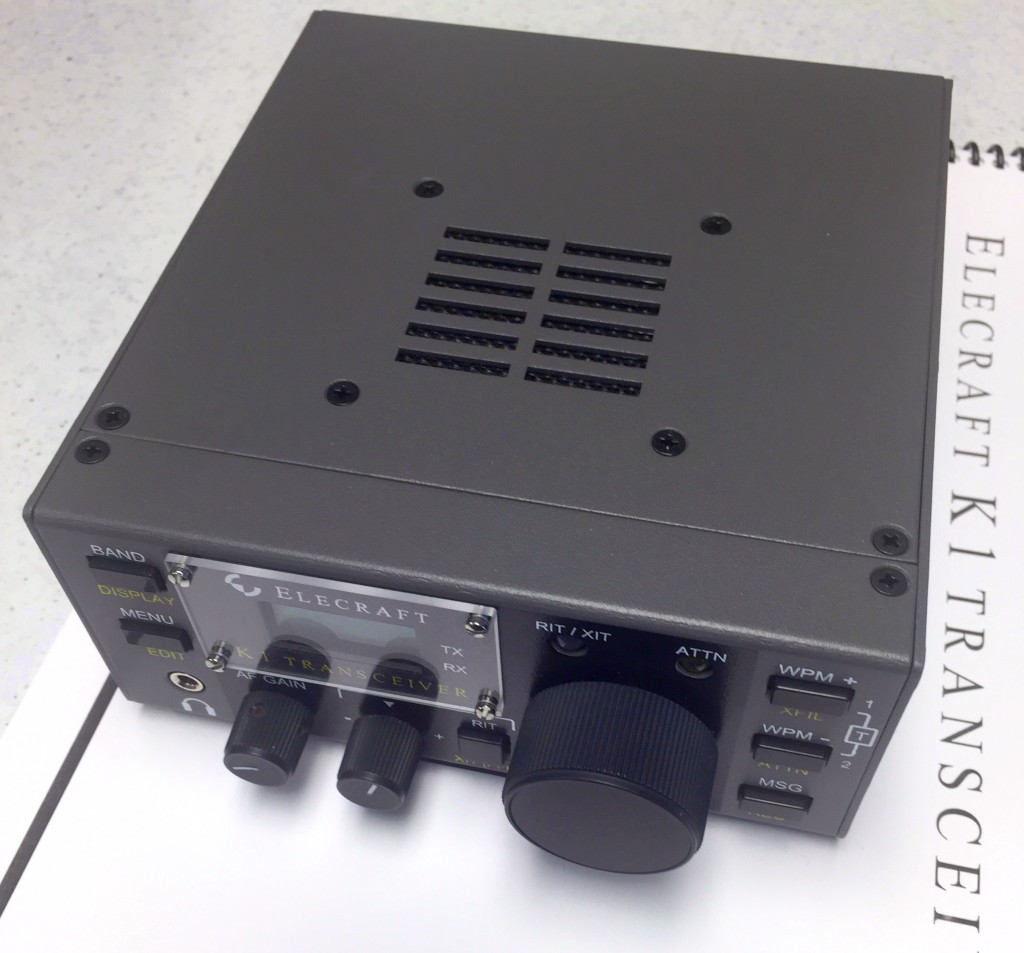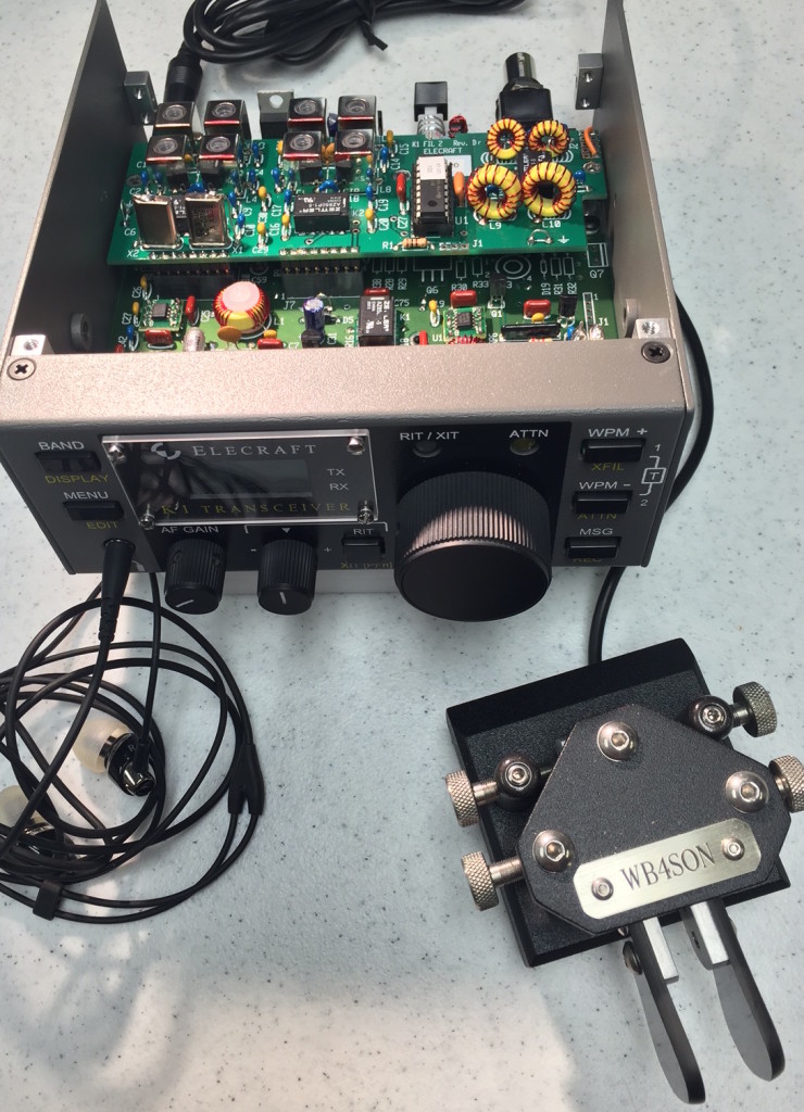
K1 RX Assembly & Tests Completed

I spent 50 minutes installing mostly mechanical components to enable the initial K1 tests. In this final RX assembly part, a coax jumper was a major pain simply because it was short yet had to be lead formed to fit tiny holes on the PCB without having conductors fray.  Pre-tinning them (I did that on one side) made the conductors hard to fit the holes.

The final reward was a series of fun tests.  Audio hiss (with a pretty strange static crackling sound every 12 seconds or so — hope that isn’t a problem) came out of the headphones, the sidetone oscillator was adjusted for amplitude and frequency, and the keyer was tested. Relays clicked when bands were changed and the attenuator was exercised.  So far all tests have gone smoothly, and only took 15 minutes to accomplish.  This brings the total K1 Assembly and Test time to 21.7 hours.

The next major step is completing the VFO assembly which involves winding a toroid.  At that point the full RX alignment can happen.  TX assembly involves fabrication of 2 toroidal transformers and installing 55 resistors, capacitors, diodes, transistors, integrated circuits, chokes, plus mounting hardware for two power transformers.  I’m going to guess 2 hours for the assembly and 1 hour for the alignment.  So 25 hours seems like the final target.

K1 Tests

Posted in Projects, QRP | Leave a comment

K1 Assembly: Three Toroids Mounted

Winding the toroids takes a bit of time, not so much the simple inductors, as the transformers with multiple windings.

Today I completed L2, T1 and T2 and mounted them.  It took 65 minutes to deal with the 8 parts (three cores, five lengths of magnet wire).  So that’s 20.6 hours and counting.

L2 T1 T2

T1 T2 Mounted

Posted in Projects, QRP | Leave a comment

K1 Passes Voltage Tests

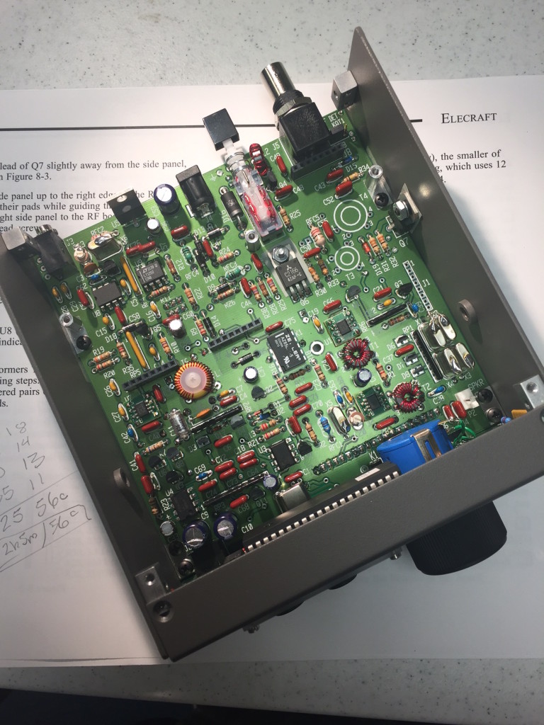
Assembly of the K1 RF Board continues.  Today, I added 49 more components in 115 minutes.  This means the RF Board assembly time so far is 7.5 hours after 193 components, and the total K1 assembly time now stands at 19.5 hours.  There are about 60 components left, including the six coils.  I’m guessing it will take about 1.5 hours to fabricate the coils; add in another 2 hours for the rest, which brings the total to 23 hours. That leaves another 2 hours to do the final mechanical assembly and alignment.  25 hours seems like a reasonable finish time now.

The good news is all the voltage and resistance tests passed.

RF Top

RF Bot

Posted in Gear, Projects, QRP | Leave a comment

XMT2XMT: WA1ABI<->WB4SON Success!

At 1903Z, Dec 21, 2015, I had a CW QSO with John, WA1ABI, on 7.020.00 MHz.  I had reconfigured the Christmas Tree Antenna so that the “hot” side of my feedline was tied to one side of the lights string, and the other side was tied to the AC Extension Cord U Ground Pin.  That seemed to bring up my signal level on the RBN, plus John was able to copy me.  I heard him booming in as S5, and he heard me at S3.

ABISONLOG

In addition to success with John, my signal was heard by more RBN stations and at pretty decent levels.

Screen Shot 2015-12-21 at 2.36.30 PM

Posted in Gear, Operating, QRP | Leave a comment

Christmas Tree Antenna

WA1ABI, John, in Portsmouth invented a new mode a couple of years back — Christmas Tree to Christmas Tree QRP.  Today I had my outside tree wired up to a remote antenna tuner and gave the XMT2XMT mode a try.  The photo below shows the remote tuner in the circled area on the bottom left.

TreeFeed

The photo below shows the tuner to Christmas Tree light feed — BNC to Banana Plug to Alligator Clips to the plug end of the lights.  The green extension cord is disconnected but the U Ground pin can be used as an earth ground if needed.

Feed2Tree

And, of course, my trusty KX3 running the show (LDG Remote Tuner box on the right — note I didn’t want to waste power in the feedline by using the tuner in the KX3)

Rig

While I wasn’t able to raise WA1ABI, or Bruce NJ3K, I heard them both, and the RBN was hearing me.

The oldest RBN was with feedline across prongs of lights.  Newer entries were with hot lead of feedline onto one wire of lights, and the shield to AC Power Ground via extension cord.

XMTREE

Here is an audio recording of Bruce and John in QSO.  All of us were running KX3s and using Christmas Trees for antennas.


Posted in Operating, Propagation, QRP | Leave a comment

K1 Assembly Burp #3

I spent 65 minutes fabricating three SMT replacement for a SA612AN chip that is no longer available in through-hole.  The process involved in stripping 24 1″ wires, somehow holding them in place while soldering them to an adapter that is about 0.3″x0.4″, not having the wires fall out of the holes during the process, not shorting them out, etc, etc, etc.

Had the DIP parts been available (and they are in small quantity from several vendors on the internet like this on:  http://www.thepartsplace.k5nwa.com/index.php?route=product/product&product_id=164 ), three of them would have taken 5 minutes to solder to the PCB.  But in fairness to Elecraft, they are not available in the larger quantities.

So Elecraft did a smart thing by making an adapter to use the SMA chip (something I have done many times for end-of-life products in my work place).  However Elecraft burped big time by not doing one simple thing — putting the holes on standard 0.1″ spacing, and using a dual male header.  This would have saved at least 45 minutes of assembly time.

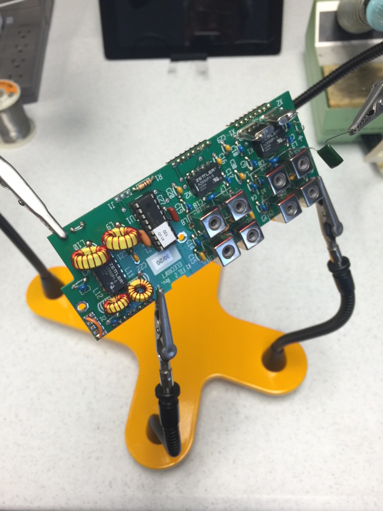
So add another 27 components to the assembly and 65 minutes.  Here are the basic items required for each chip (insulated wire is stripped and cut to create 8 legs):Burp-3-1

Somehow the adapter has to be held, the wires kept in place, and solder applied without shorts — easy to do if you have four steady hands.  Almost impossible with two.  So I used needle nose pliers to hold the adapter, and put it into my PanaVise so that it was mostly parallel to an arm, which acted as the stopping point preventing the wires from falling out. Note: Elecraft’s suggestion of bending the wire at the top is NOT practical as the wire will rotate and create shorts between pins.Burp-3-2

The final Rube Goldberg product looks like this (very un-Elecraft-like:Burp-3-3

In the spirit of not complaining without providing a solution, how about something like this (SMT adapter PCB mated to 8-pin screw machine male-male adapter?K1-Burp-4

Posted in Gear, Projects, QRP | Leave a comment

Another Surprise From the ARRL

I guess the January 2016 QST is hot off the press.  I received an express envelope with three pristine copies today as a courtesy for a brief piece in Technical Correspondence [pages 72 & 73].

My father was a journalist, working for the Lexington Herald Leader for many years after owning a small weekly paper in Tennessee.  If he were still with me, I suspect he’d be smiling.

QST Jan 2016

Posted in From the OM, Gear, History | 1 Comment

K1 Assembly Continuing

The K1 RF Board assembly continues to move forward.  Today, 24 components were installed in 70 minutes.  Only a third of the RF board remains, with a bit under 16 hours spent so far.

IMG_3604

Posted in Gear, Projects, QRP | Leave a comment

K1 Assembly Burp #2

I had a chance to install a dozen components today, but it took about 50 minutes.  This was because the two adjustable caps (C13 & C20) as supplied do not match the manual description or silkscreen outline.  Elecraft specifies a particular mounting orientation.

Examination of the schematic shows that both caps are trimming oscillators, and neither leg is ground referenced, so I’m not sure why there is a concern over orientation.

Like many small trimmer caps, the adjustment screw (rotor) is attached to one of the two pins, and the stator is on the other.  So approaching the screw might couple in some stray capacitance making it hard to set things.  Usually one tries to have the rotor ground referenced to avoid that.

In both cases, one side of the cap is attached to the crystal, and the other is going into a pin on the SE612 mixer/oscillator chip.  While I don’t think it will matter much, I figured avoiding having the rotor end on the crystal would be best.  In the photo below the stator is colored red and is a rectangular bump, so maybe that is the “flat” side.  in any event, the flat side on the silk screen goes to the crystal.   So this is how I installed them, red side to the flat.

K1 Burp 2

Posted in From the OM, Gear, QRP | Leave a comment

K1 RF Assembly Continuing

After 2 hours 20 minutes of assembly time, there are 81 components on the RF board (a rate of about 1.75 minutes a component).  With 251 total components on the RF board, I’m about a third of the way away.  Some 48 of those (transformers and SMA chip adapters) require quite a bit of fiddling.  So call it another 5.5 hours of assembly time to go.  As I have 14.5 hours invested so far, that would be a total of 20 at the current rate.

RF at 2h20m

Posted in Gear, Projects, QRP | Leave a comment