My last AO-73 QSO was about 10 months ago. Part of the reason is laziness — it is time consuming to relocate the uplink offset each time I try to work the bird. I’ve read that the uplink passband is unstable with temperature changes (like going into eclipse after being illuminated). The downlink is very stable by comparison.
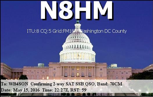
The good news is I had a QSO with W8IJ in PA tonight. The better news was I found my signal fairly quickly, only about 1.5 KHz from the Uplink Offset I used last August.
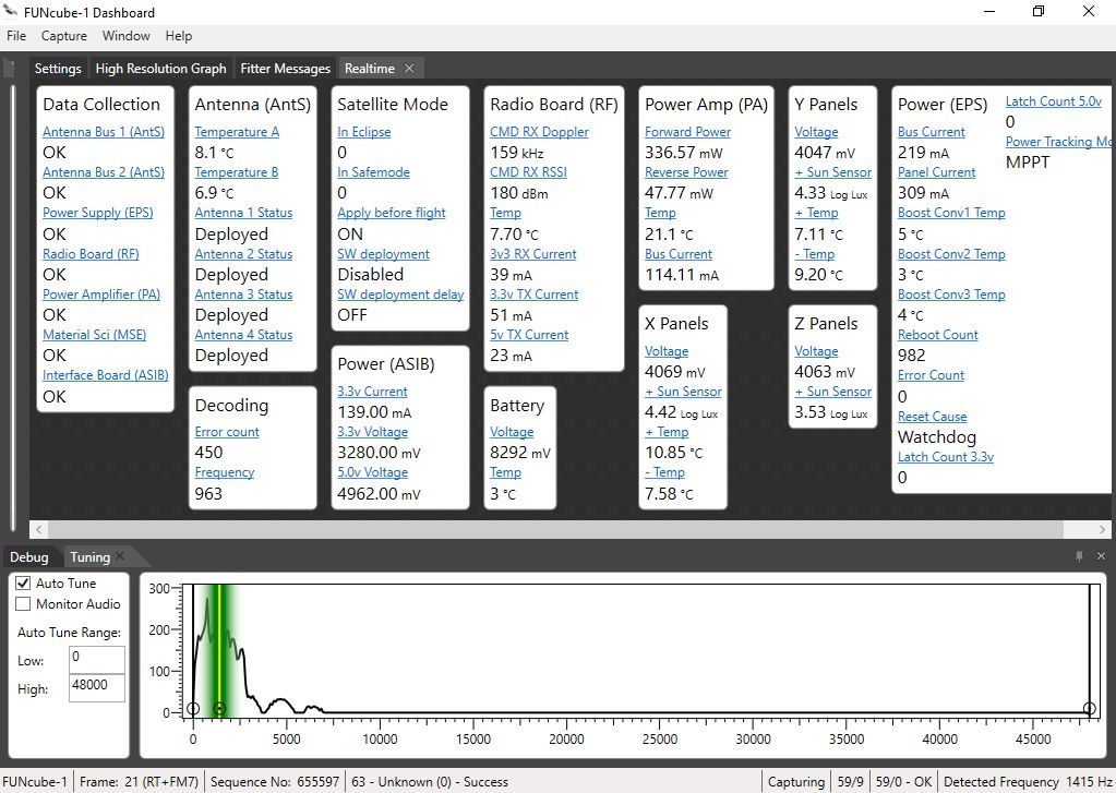
Tonight I was sending a CW signal on 435.161.38 (at the satellite) and hearing it on a downlink of 145.957.42 (from the satellite). When I say “the satellite”, I mean what the frequency would be at the satellite taking into account Doppler adjustments. This is critical because the frequencies of operation of a satellite are specified at the satellite.
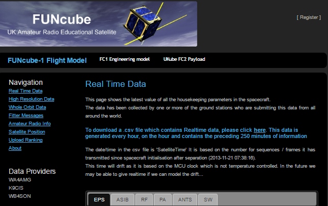
If you look at FUNcube website, the published info on the transceiver is:
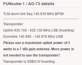
Right off the bat you can see something is wrong! Supposedly the uplink ends at 435.150. But I was transmitting (at the satellite) a frequency of 435.161.38. According to the published spec, it should have been 435.142.58. That’s a 19 KHz discrepancy!!!
MANY people have reported this, but I’ve never seen it acknowledged officially — No doubt expert satellite users simply integrate the required offset into their process and never think about it again. But it sure as heck throws off someone who doesn’t expect it to be that far off.