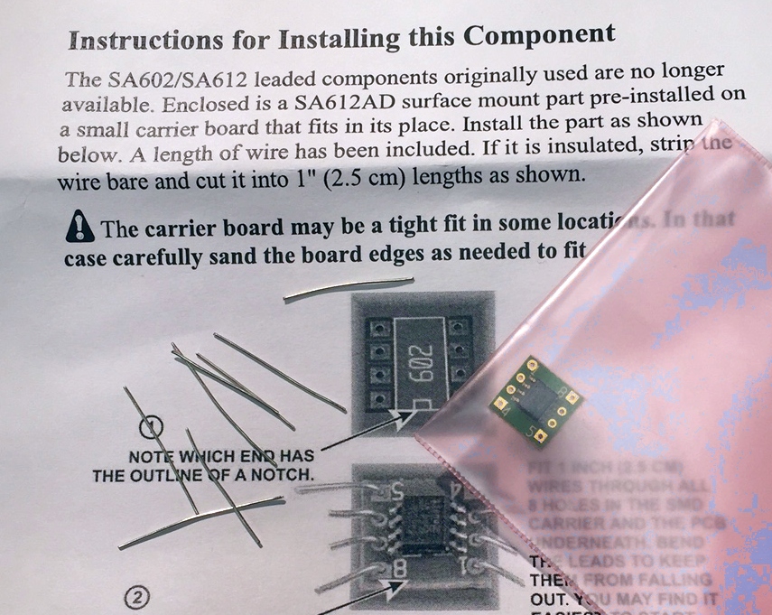
I spent 65 minutes fabricating three SMT replacement for a SA612AN chip that is no longer available in through-hole. The process involved in stripping 24 1″ wires, somehow holding them in place while soldering them to an adapter that is about 0.3″x0.4″, not having the wires fall out of the holes during the process, not shorting them out, etc, etc, etc.
Had the DIP parts been available (and they are in small quantity from several vendors on the internet like this on: http://www.thepartsplace.k5nwa.com/index.php?route=product/product&product_id=164 ), three of them would have taken 5 minutes to solder to the PCB. But in fairness to Elecraft, they are not available in the larger quantities.
So Elecraft did a smart thing by making an adapter to use the SMA chip (something I have done many times for end-of-life products in my work place). However Elecraft burped big time by not doing one simple thing — putting the holes on standard 0.1″ spacing, and using a dual male header. This would have saved at least 45 minutes of assembly time.
So add another 27 components to the assembly and 65 minutes. Here are the basic items required for each chip (insulated wire is stripped and cut to create 8 legs):
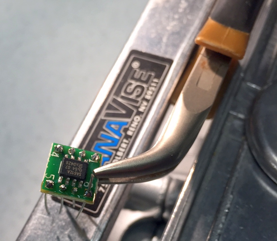
Somehow the adapter has to be held, the wires kept in place, and solder applied without shorts — easy to do if you have four steady hands. Almost impossible with two. So I used needle nose pliers to hold the adapter, and put it into my PanaVise so that it was mostly parallel to an arm, which acted as the stopping point preventing the wires from falling out. Note: Elecraft’s suggestion of bending the wire at the top is NOT practical as the wire will rotate and create shorts between pins.
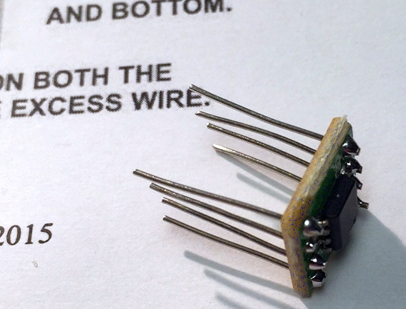
The final Rube Goldberg product looks like this (very un-Elecraft-like:
In the spirit of not complaining without providing a solution, how about something like this (SMT adapter PCB mated to 8-pin screw machine male-male adapter?


