Shortly after being on the RF side of things for a successful ARISS contact in May of 2016, I decided to volunteer to become a technical mentor for ARISS. After shadowing Dave Jordan AA4KN (a mentor’s mentor) for an ARISS event on Long Island, I was assigned to support the Museum of Science and Technology (MOST) in Syracuse NY, which had partnered with Danforth Middle School, Ed Smith Middle School, and the Central Village Boys & Girls Club of Syracuse.
Within seconds of the predicted AOS at 9:09 AM local time (14:09 UTC, Feb 23, 2018) the voice of Astronaut Mark Vande Hei could be heard over the live stream (and copied locally at S9+ using my eggbeater antenna). All 17 questions were asked by the young students at the museum and answered by a very engaging Vande Hei.
Congratulations to the staff of MOST and all the volunteers that made this event a success, and especially the ARISS organization for making this possible.
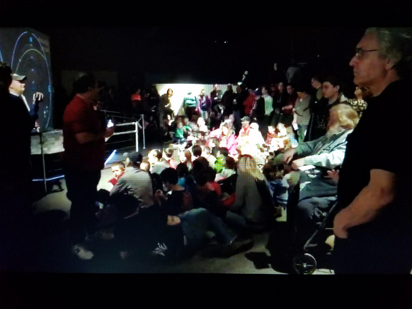
View of the crowd at MOST during their AIRSS Contact on Feb 23, 2018