
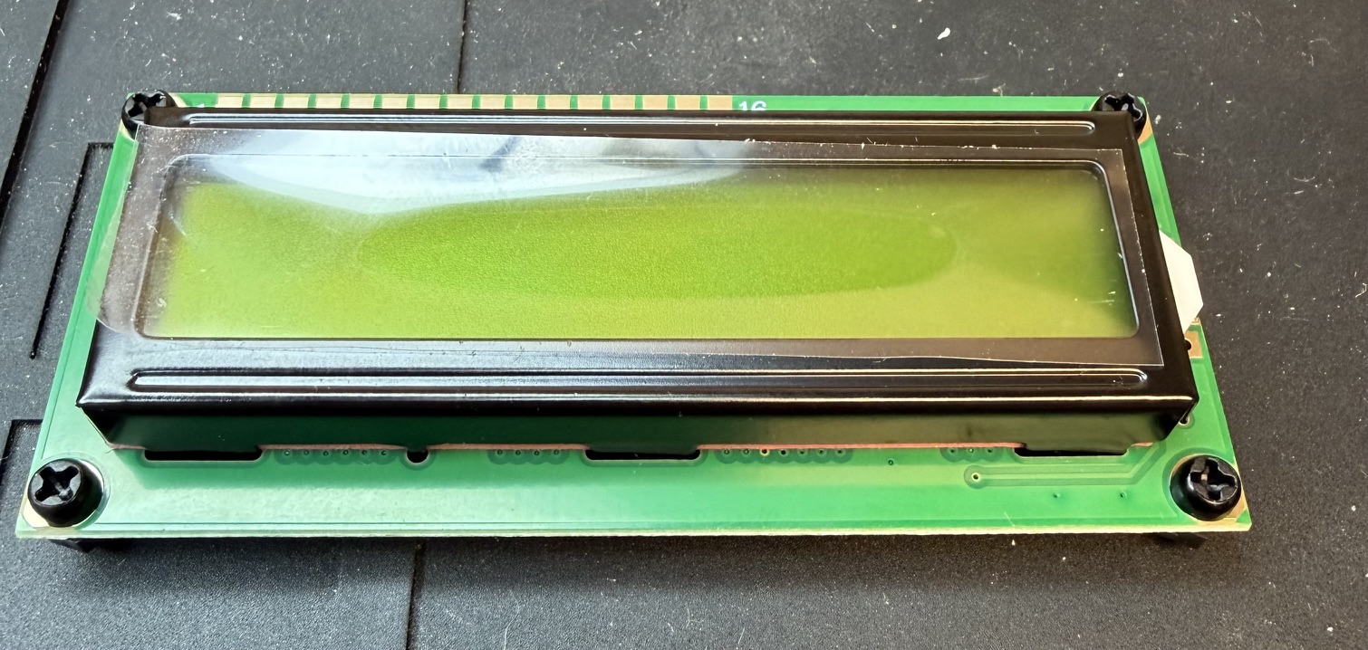
Yesterday, I had a bit of time to finish construction of the Pebble HF. I’m embarrassed to say that I put another 1.75 hours into it. In my defense, I was obsessed with getting the LCD perfectly parallel to the PCB and at the correct height. Figuring that out and hunting for the parts took an hour.
My solution was to use some nylon M2.5 screws and nuts to create posts that would fit into the mounting holes on the PCB. Since the nylon nut was the exact height of the 16-pin header, it kept all four corners at the correct height. When I was all done, I remove the two screws and nuts on the left side as those holes mate with pins on the back of the case. I left the two on the right in place.
The only observation I would make is that the assembly instructions recommend putting the long pins of the header thru the PCB and the short pins thru the LCD. I did that, but discovered that the long pins fall into a “valley” on the back of the PCB, which is VERY difficult to reach into with a soldering iron. The long pins actually make that more difficult. Besides the two toroids, the variable resistor that adjusts the LCD bias and a capacitor are quite close to the header pins as well. Look at the column of header pins in the photo below.
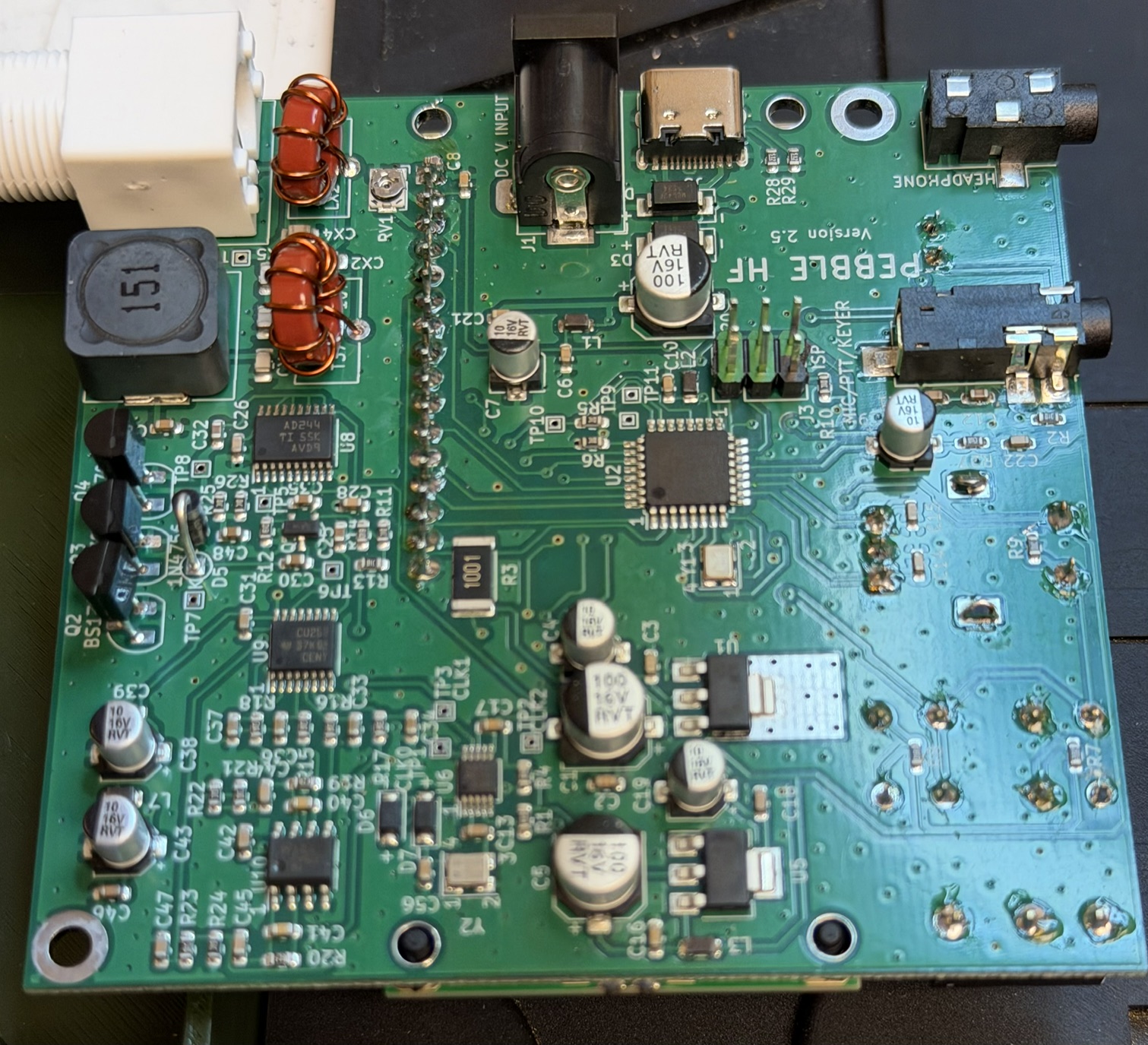
Having said that, I think reversing that connector (short pins thru PCB and long pins thru the LCD) would make soldering much easier, the longer pins would have to be trimmed off to avoid interference with the front cover – but that would be easy to do as everything is open.
In that same photo above, you can see that I stupidly did not orient the ISP connector correctly – I never looked at the part, just figured it was a standard 6-pin connector. It wasn’t – five of the pins have a green color, while one is black. That black one SHOULD be on pin 1, but I rotated it 180 degrees – oops, have to remember that when I program things!
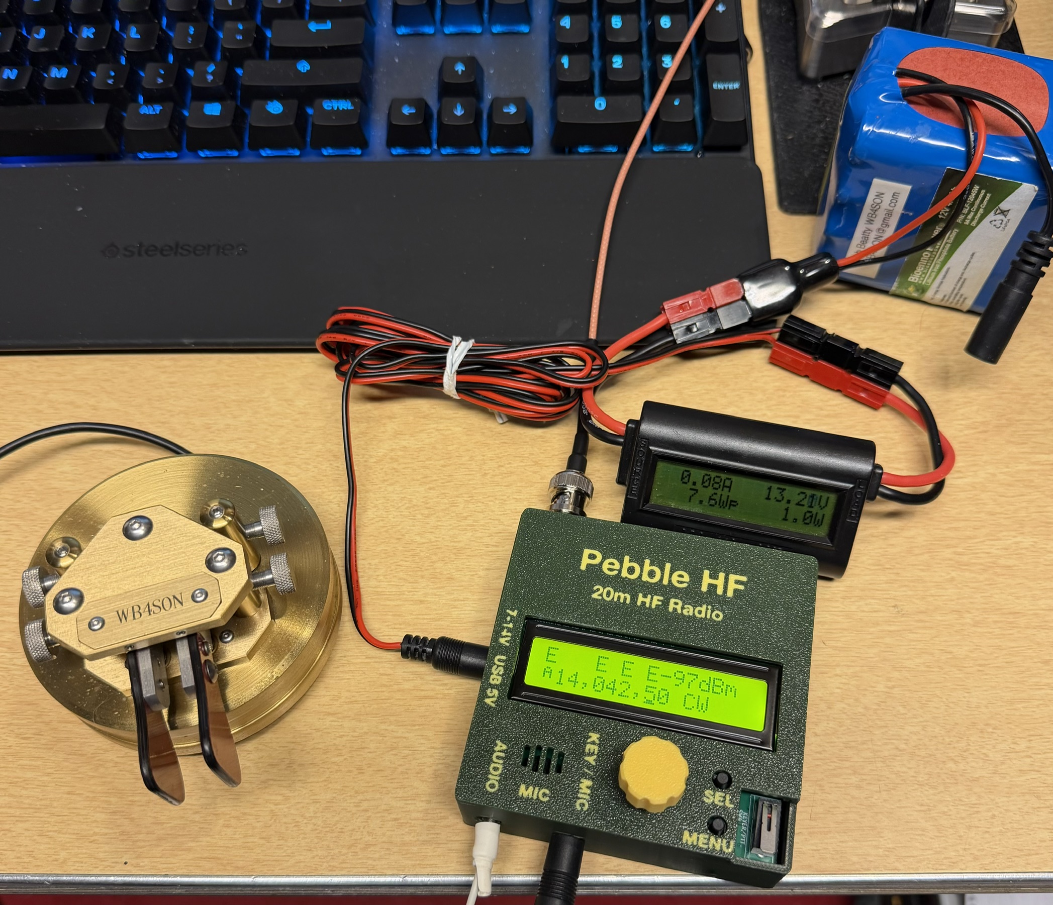
The Pebble came to life at 5:33 PM EDT on May 21. I spent a total of 2.5 hours elapsed time doing the assembly. At least an hour of that time was not necessary. That means that someone else with bad eyesight and hand tremors can easily build this kit in 90 minutes. A younger ham could probably do it in 30 minutes.
My quick checks on the bench revealed the following:
- LCD bias control had to be rotated about 90 degrees clockwise to see the display and requires a very fine straight blade screwdriver (eyeglass screw size).
- RX Current 80ma
- TX Current 560ma
- Power out 4.6 watts (at 13.2 volts)
- RX sensitivity is a bit weak. A 1uV (S3) signal is barely discernable above the noise floor. A 50uV signal (S9) is quite strong
- RX opposite sideband suppression is weak. When running CW, tune up to find the lower frequency signal
- The CW decoder is very decent
- All features have been checked at this point other than the USB connector.
Those measurements are quite impressive for a simple $50 radio. It was clear to me that it should be easy to make contacts if I stick to stronger signals.
My first contact was at 1917UTC this afternoon. It was on 14.0425 MHz with Connor, W0DOS who was in US-10557 in Missouri. We both exchanged 599s (and I heard him coming back to other stations with 549s), so the little Pebble did its job. I would like to say I worked him on my first call, but I didn’t, and the reason was entirely my fault. The RX has some attenuation of the unwanted sideband, but not like a $5000 radio. I had tuned him in on the higher frequency note. That put my signal about 1.5 KHz too high. When I retuned him to the lower frequency note, he did come back immediately. So I learned to always tune from the bottom up and not to go through zero-beat.
My thanks to Tom KS4CR in SC, and John N0EVH in MO for another two QSOs!


Love it
I gotta have one of these! How can I get one fast???
Kq4fm
They have started shipping but it is a large backlog. You must register for one. Go to the pebblehf.com website and the sign up is towards the bottom of the page