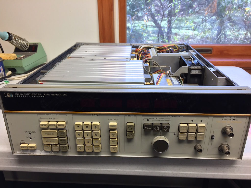
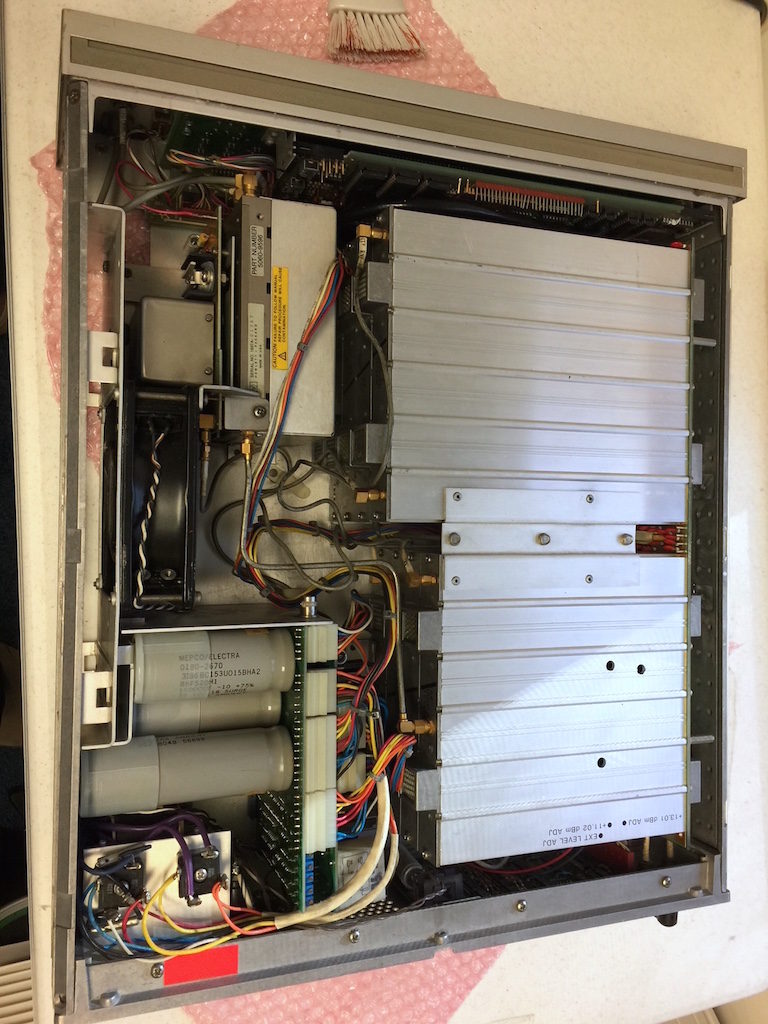
I’ve always been sort of a time nut, but that’s pretty closely related to frequency. The ARRL helps to sponsor a periodic Frequency Measurement Test, usually held in April and November. A good friend of mine, John WA1ABI, always participates and usually has outstanding accuracy. I’ve always been fascinated by that, so I went looking for some surplus gear.
My plan was to us a milliHertz resolution frequency synthesizer to generate a carrier of known frequency that was manually adjusted to be within a few hundred Hertz below the unknown signal. A RX in AM mode would produce a heterodyne audio beat note equal to the frequency difference. Add the audio frequency to the known frequency and the unknown will be revealed.
I put my sites on a HP 3335A signal generator. This is a massive beast that is about 40 years old (would have been new when I started my first engineering job in the late 1970s). They are fairly common on eBay, and can be found in various states of disrepair. I happened to locate one locally from someone who had worked on closing a capacitor factory in Massachusetts. The good news was it was inexpensive. The bad news it was sort of working and absolutely filthy.
After several hours of scrubbing the covers, they now are no longer sticky to the touch and dirty, but they show 40 years worth of wear and tear. The unit powers up and generates a fantastically stable/repeatable signal (the internal 10 MHz source, once warmed up for an hour, is within 44 milliHertz of spot on — that’s 4.4 parts per BILLION). It is pretty amazing to be able to change any of the 10 digits by one and see that exact change show up in the output.
But there is a significant problem. The unit randomly resets itself every 30 – 300 seconds. At that point the frequency is reset to 1.0 MHz, and the output level drops down below -80 dBm. The reference oscillator remains running, and within a fraction of a second of entering the frequency and amplitude via the keypad, it is up and running again.
After going through the service manual and schematics, it appears the only reason this would happen is if there were a voltage issue with the internal 5 volt supply. That could cause the 6800 CPU to reset. The 3335A never really powers off fully. The unregulated supplies are always on as long as the power cord is plugged in. It is highly likely that 40 years of this has fried the large power supply caps, and that would make the 5 volt supply unstable. We shall see!


Dear Robert,
I have also just acquired an HP3335 for personal use which is working Ok at 10MHz and above but the minute I set it to anything less even a Hz the O/P has an inverted perfectly synchronised and at the same frequency -ve tip of the sine wave in it!
I have not investigated it yet but on the off chance that you might have experienced similar I thought I’d get in touch.
Yours Sincerely – David Hadaway G4MCM
based in Reading Uk, I work in Southampton.
I sail, sometimes with the visually impaired, have an interest in Navigation, electronics, HPIB , and hybrid cars.
Hi Dave,
Boy I wish I could help you out. I actually bought two of them and did some board swapping to get one working, plus replaced the filter caps that were on the power supply and the motherboard.
Having said that, the first one I tried out, would work for a few minutes then go all 8’s on the display. I discovered that there is a voltage detector circuit on the main control PCB (the one with the CPU on it), and I could watch that signal drive the board into reset. Sure enough several of the voltages were on the low side. That was why I replaced the big bulk caps on the power supply, as well as the smaller bulk caps that are located on the back of the big motherboard. At that point things were working correctly. As I recall that unit had some funky stuff that showed up as I adjusted up/down from 10 MHz — I swapped out the ECL board that for the PLL one at a time until the problem went away.
Sadly it died on me, and rather than spend another $150 to $200 for another one to swap parts out of, I decided to try a Siglent SDG2048x. That works just fine. I can set a frequency to a resolution of 1 mHz (so 9.123 456 789 MHz) and as log as it is slaved to an external 10 MHz reference it really is 9.123 456 789 MHz).
First step for ANY HP gear that came from the 1980s is to check power supplies and expect to have to replace the caps. Good news is the caps they sell today are smaller so the fit isn’t an issue. I was able to find caps with similar screw spacing on the power supply.
73, Bob, WB4SON
Hello David,
My name is Harke, PA0HRK, and I saw your work on a HP3335A. I also seem to have a problem with this nice instrument, although it works ok at first sight. I suspect something wrong in the reference unit. I have downloaded the Repair manual but I cannot find a documented way to take the box containing the pcb’s out. Can you give me a hint?
Many thanks,
Harke
I wish I could, Harke, none of the manuals I have document assembly or dissembly, and it is a rather complicated mechanical beast too. I tore mine down to replace all the old caps, and put it back together. I’d be surprised if your reference oscillator is the issue (unless you have no output observed on a scope). Far more likely are power supply issues due to bad caps, or sometimes failed ECL logic. Good luck!
Thank you for the encouragement.
I have fixed it this evening. The PSU rails looked ok on a scope but the symptoms on closer examination of the main O/P started as low as 5 kHz and up to anything below 10MHz worsening as the frequency increased. Studying the circuit description and diagrams I went straight to repair section M and A 6 module placed measurement taps on wires on R26 near I/p of 1kHz to 10MHz amp, on R48 and TP6. The last 2 showed the same distortion on negative of sine wave but the R26 tap was fine this eliminated anything in Lservice section L the previous mixer stage and left me looking around Q5, Q6, Q7 and Q8. Not having extenders was going to make further live diagnosis a bit long winded I thought, however I thought it might be one of the PNP transistor Q6 or Q7 having a offset/ headroom related problem but not being able to easily measure DC conditions I decided to check C24 and C23 fist.
As luck would have it the first one C24 I unsolder to check was O/C!
Annoyingly I am in the process of relocating anything electronic into my loft workshop and could not find my box of Tantalums purchased for such eventualities Needless to say the 3335 is a bit big so I have it on the dinning room table whilst my partner Lyn is
away for the weekend. Not wanting to go to bed till case proven I found a 47uF 50v conventional electrolytic to fit temporarily.
It’s now working fine. I will probably go through the whole board if not all the modules measure and replace all of them. The reason being that 2 years ago at work we acquired 4 Datron 4700 series Calibrators each with a large number of failed tantalum capacitors.
They were a bead type and some had blown off their tops whilst others had just discoloured. In the end we replaced all of them on each of the 10 pcbs, About 30% of them were faulty. I have never replaced so many well over 200!
I have never seen the flat electrolytics that are in this 3335 in any other HP kit but then again it’s one of the earliest designs I have worked on and HP equipment in general is very reliable.
A useful tip is to solder smal test leads to points you need to measure when the module is in situe and feed them out through the cooling honeycomb
It may take me some time to update you but when I have investigated the rest of the A6 module for possible weakening caps I’ll post a further review of my findings.
Best 73’s G4 MCM