There’s a joke in there somewhere…
Yes, size does matter when it comes to Toroid diameter (which also has an impact on winding geometry), maximum wire size, etc. All things which impact the Q of the circuit.
I went back to my original S8050 Transistor, and swapped out my T37-2 inductors for T50-2 inductors wound with 15 turns of #20 wire (13″ of wire, measuring 1.2 uH). This allowed the winding to be single layer and evenly spaced (the smaller T37 cores had to go to two layers and were really jammed in there).
I had seen Q readings at 100KHz of 20 for the T37-6, 25 for the T37-2. The larger T50-2 inductors had a Q of 45. The higher the Q, the lower the insertion loss, so larger cores with heavier gauge wire are better. That’s the same conclusion that is reached in the Micrometals Q Curve App Note (I’m using Micrometals cores). The filter response curve was very similar but at 7.040 Mhz the loss was now -1.97 dB, about a 0.1 dB improvement.
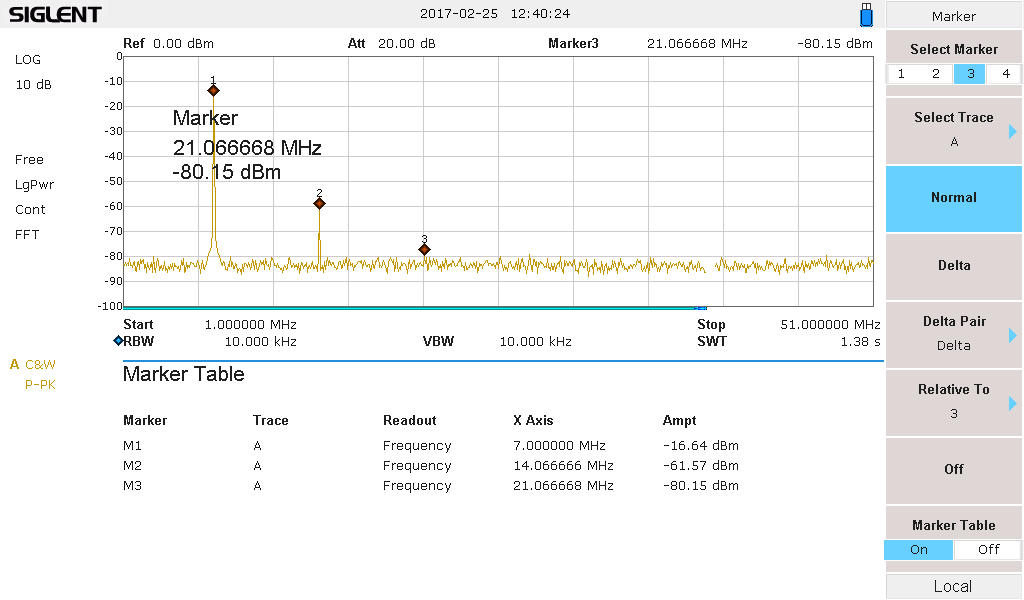
With the filter using the T50-2 cores the spurious response output looks like this (Meter reading just about 270 mW, 2nd harmonic down -45 dB, fundamental at 220 mW).
| T37-2 17 turns #20 | T50-2 15 turns #20 | |
| Meter Power | 250 mW | 270 mW |
| 7.040 MHz | -16.6 dBm | -16.7 dBm |
| 14.08 MHz | -63.0 dBm | -61.6 dBm |
| 21.12 MHz | <-80.0 dBm | < -80 dBm |
Proving again that basic physics never gets old, here is a great reference from Boonton Radio Corporation, circa 1955, that describes a Q-Meter and how you can evaluate components. (Thanks to John, WA1ABI, for this great article!)

