Did a Common Mode Current Choke Help?

I did before and after testing using the big coax choke from COMTEK, and it did not help.  The noise I was seeing on the 40 and 15-meter bands was still there and at the same level.

Unfortunately I was no longer able to use my Flex 6600M on 40-meters as it refused to find an acceptable match (in the past it would be about 1.5:1.  Not the fault of the CMCC, of course, but an indication that my station ground is part of the antenna system, and was being isolated by the CMCC.

Back to the plain-old coax jumper, and some head scratching regarding my station ground.

Posted in From the OM | Leave a comment

COM-CFC-50A Choke Test

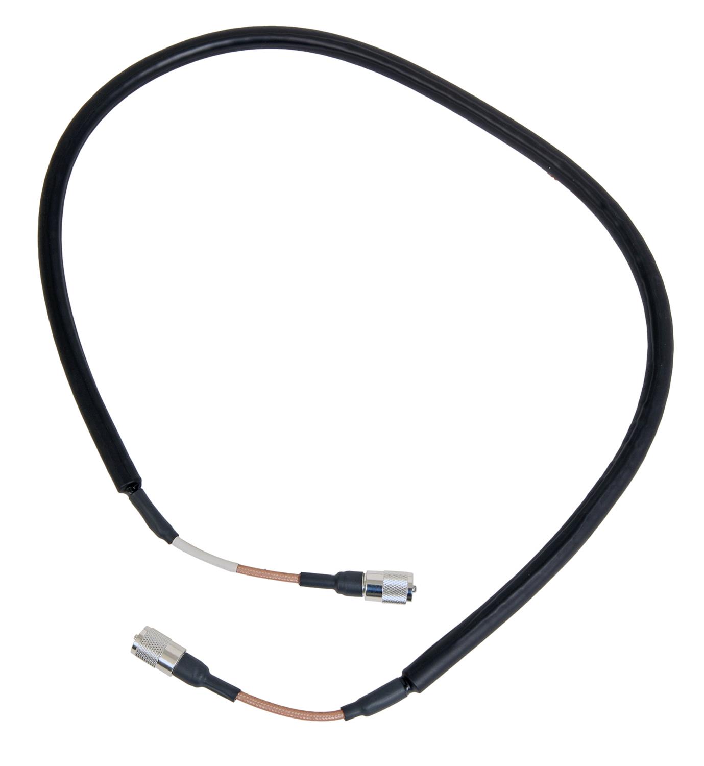
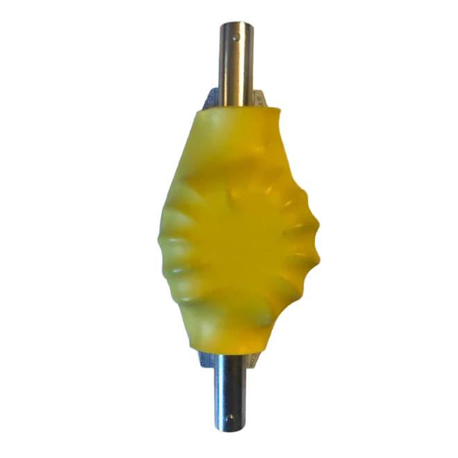
I have a couple of other Common Mode Current Chokes laying around the shack.  One of them is the COMTEK COM-CFC-50A.  It’s a beefy choke, rated at 5KW – about 6 feet long and covered with 75 ferrite beads over some Teflon RG-400 coax.  It isn’t a field device, for sure, and weighs in at about 3 pounds.

COMTEK COM-CFC-50A - COMTEK Current Feedline Chokes

I’ve been having some issues with noise on 40m, and wanted to see if a Common Mode Current Choke would help reduce it.  Since I sometimes run my KPA-1500, I needed a choke rated for power.  That said, I was curious how it performed, so I ran the identical tests on it, that I did with the PackTenna PT-202/PAK-103, and this is what I saw:


  • 33dB on 80m
  • 36dB on 40m
  • 38dB on 20m
  • 33dB on 15m
  • 30dB on 10m

I actually had a bet with myself that this would outperform the PackTenna – I suppose it depends on your perspective, the COMTEK choke has a slightly flatter curve, especially evident at higher frequencies, which is likely better for my home station, but for the most part it has slightly less reduction in common mode current.

Posted in From the OM | Leave a comment

PackTenna CMC Test Results

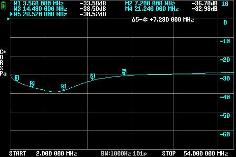
Using the Halibut Electronics CMC Test Rig, I hooked up the PackTenna PAK-103 In-Line Common Mode Choke (rated for 100 watts).  The nanoVNA was calibrated using the Open/Short/Load on the Test Fixture.

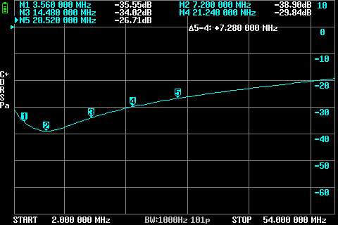
Here are the results with some markers on the screen close to various ham bands:


Basically it provides the following CMC reductions:

  • 35dB on 80m
  • 39dB on 40m
  • 34dB on 20m
  • 30dB on 15m
  • 26dB on 10m

Since I’ve often had issues with base loaded whips on 40m, this seems to be a pretty effective device, reaching commercial-level performance on 40m.

Posted in From the OM, Testing | Leave a comment

Common Mode Choke Test Rig

Having been in the hobby for more than a few decades, various issues with RFI in the shack are often attributed to “common mode current” – that is a signal that is injected into our coax in such a way that it impacts both the center conductor as well as the shield together (hence “common”).  This can happen when a feedline is in the radiation pattern of an antenna.  Other noise signals can be coupled into our coax when it runs along the ground.

Its pretty easy to determine if a common mode choke is effective – just put it into the feedline and see how things respond.  But that always left me wondering which common mode choke performed the best.

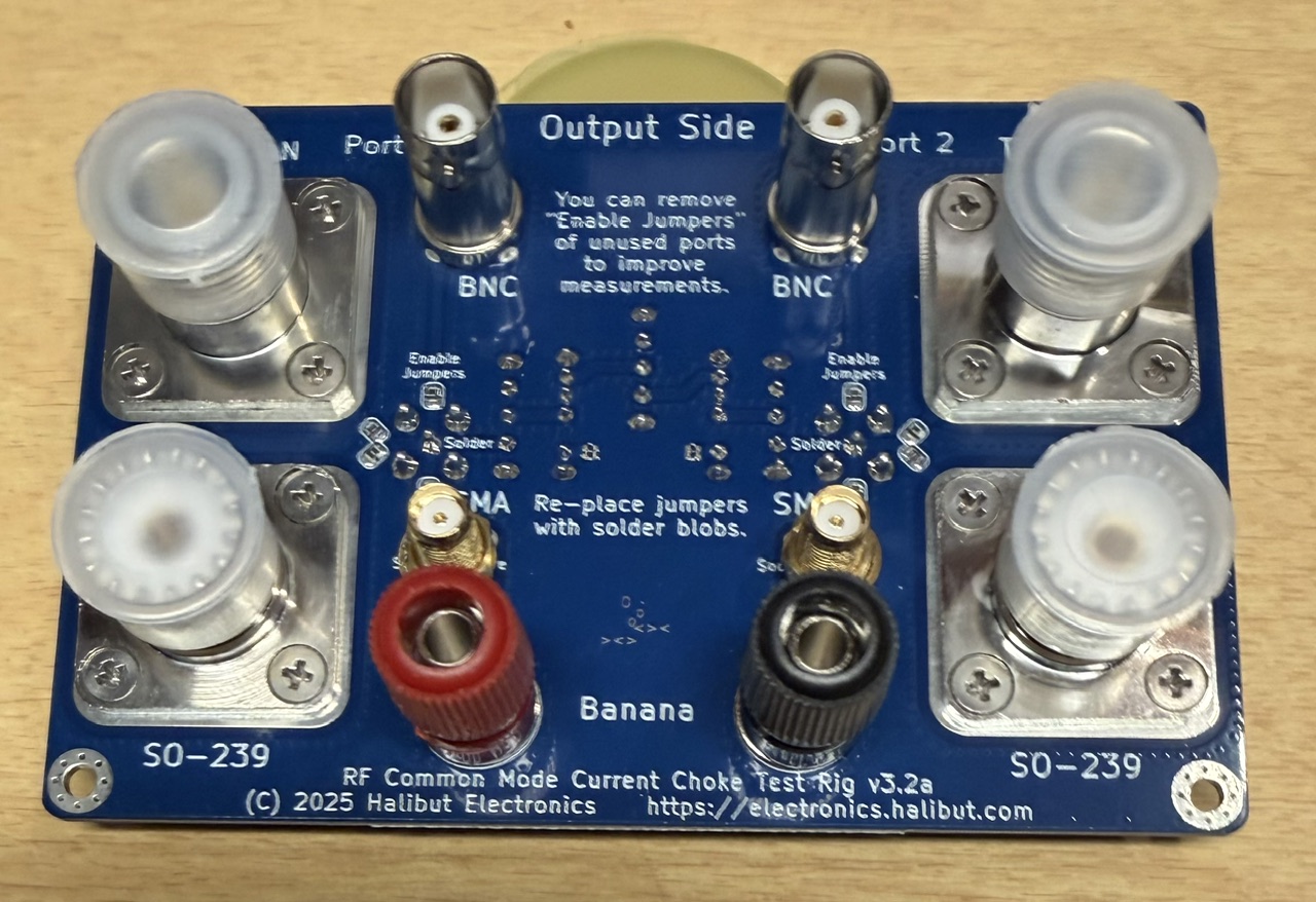
Halibut Electronics has developed an inexpensive test rig that allows you to test various common mode chokes.  Essentially it is a set of different connectors (SMA, BNC, SO-239, N, and Banana Jacks) that allow pretty much any choke configuration to be tested.  It is used in conjunction with a VNA to measure the actual common mode reduction.  Thoughtfully it even includes a switch that allows you to calibrate the VNA (open/Short/50 ohm).

Posted in Testing | Leave a comment

A Fantastic Activate All RI Event!!!

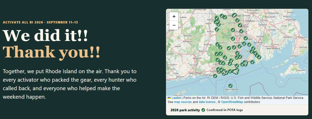
Hats off to Brian K1BS, Brian N1NW, and Rob N1RWJ and the crew of the RIOPTA.org and the groups.io RI-POTA group.  These three fine gentlemen put together a fabulous 3 day long event and successfully put all 61 Rhode Island Parks on the air.

Sadly I was under the weather and wasn’t able to activate a park, but I did hunt dozens of the activators.  In fact I went from needing 14 parks to get Hunted All RI Parks, down to the following 5:

  1. US-2881 World War II veterans Memorial State Park
  2. US-5484 George Washington Memorial State Forest
  3. US-6990 Nicholas Farm Wildlife Management Area
  4. US-7518 Kimball Wildlife Refuge
  5. US-7715 Durfee Hill Wildlife Management Area

By the way, 41 activators participated, including 11 that are members of Newport County Radio Club, with 5,449 logged QSOs (as of this posting).

Posted in Activation, POTA | Leave a comment

WA4MCMkits PSR-100 Mk2 Portable Sat Rotor Kit

Years ago there was a company called “Portable Rotation” that made a very decent portable AZ-EL rotor.  It ran off of 12 VDC, it wasn’t as heavy as a Yaesu  Az/El rotor, but it was a hand full.  It required a pretty hefty tripod to hold it.  I  mounted a pair of Arrow “Alaskan” beams on it (one side 2m, the other 70cm).  Between the antennas, rotor, tripod, and cables, it was probably close to 50 pounds of stuff, and took up much of my trunk.  It worked very well, but I wasn’t willing to spend 45 minutes putting it together and another 30 minutes pulling it apart to make satellite contacts in the field.  So I stopped using it.

Since then, all my Summer and Winter Field Day satellite activity has been using the smaller Arrow crossed beam.  Many folks hand-hold it, but I mount it on a camera tripod and point is where the bird will be about 1/3 of the way through the pass.  That gives me excellent S9 signals on the linear birds, and a decent chance to make it through the chaos of an FM bird.

But for years a little voice has been saying “What if there was a smaller, lighter, easier to use Az/El rotor that was optimized for the 3×7 Arrow crossed beam?”  Oddly enough a Google AI+ search came up with a kit for exactly what I was looking for.

Don Friend WA4MCM has designed a kit called the PSR-100 Mk2 Portable Satellite Antenna Rotor Kit.  I ordered one on Sept 1st, and it arrived on Sept 5.
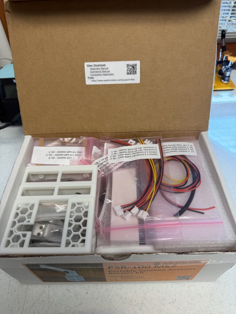
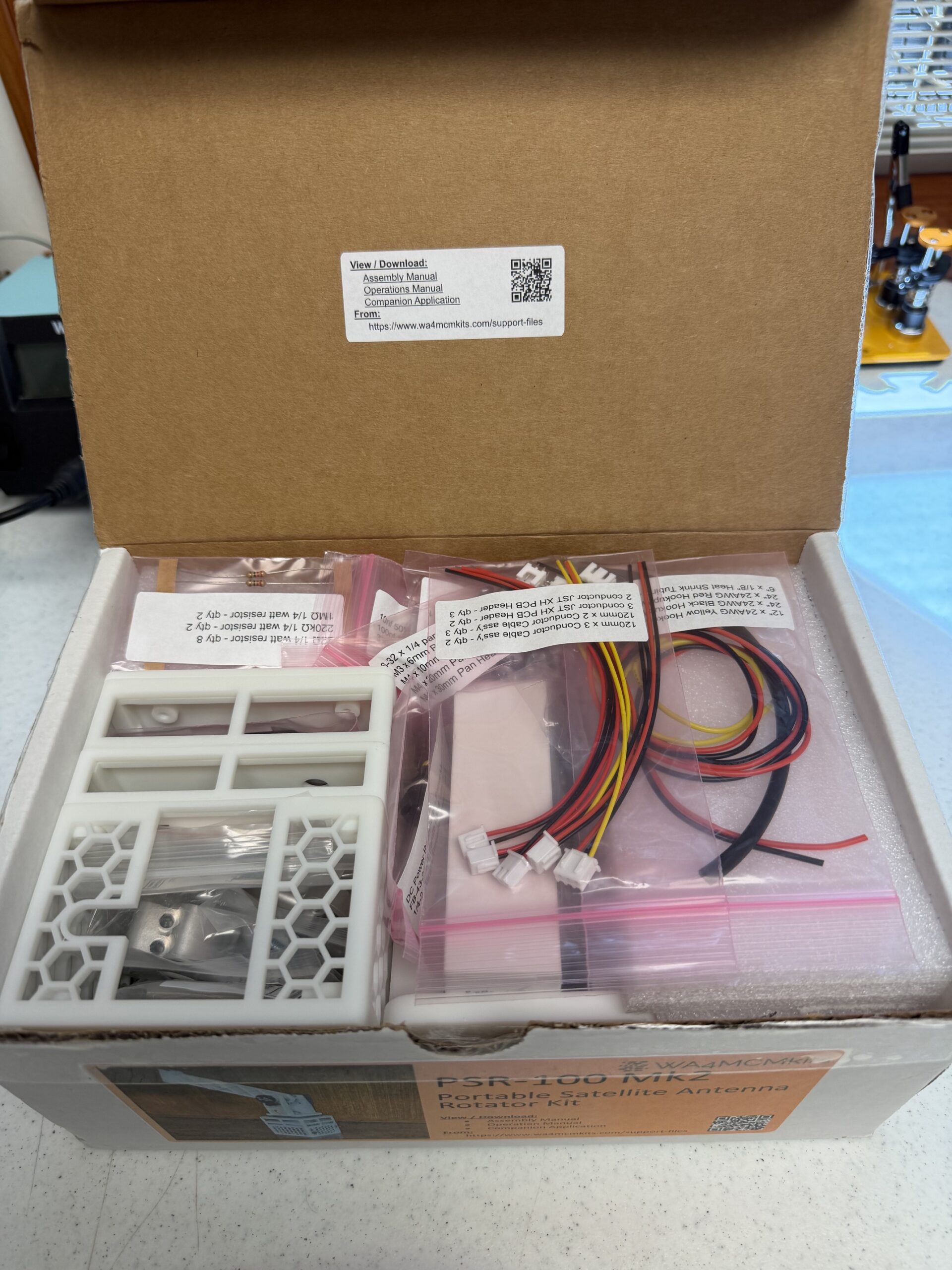
The above photo shows the box that arrived in the mail, all 3+ pounds of it.  Don used every cubic inch of space fitting all the parts in.
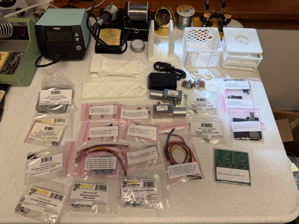
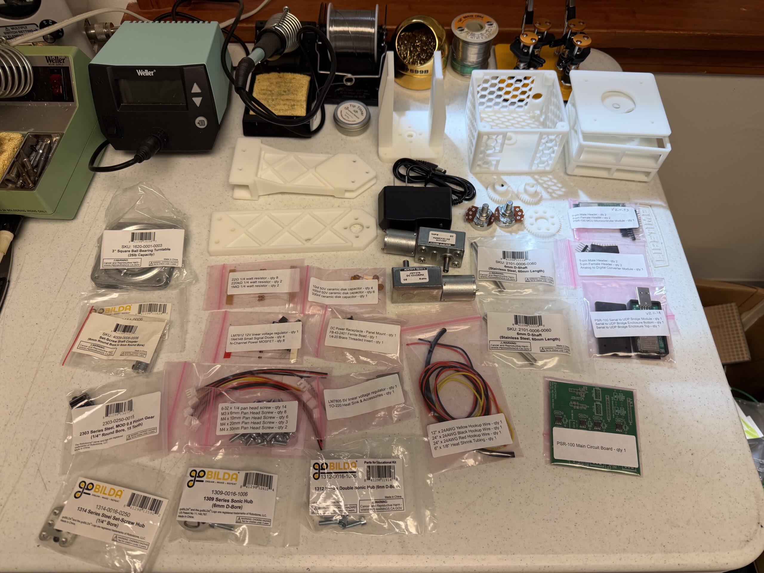
The photo above shows all the carefully bagged sets of parts that were in the box.  I counted 34 bags and resin parts.  Speaking of the plastic parts, they were VERY well printed, much higher resolution that I am used to, and appear to be quite robust.

In terms of electronics, a few SMT parts are on the PCB already, but I’m surprised the resistors and capacitors (23 of them) weren’t mounted as well, but they are through-hole.  There are a dozen small headers to solder in, a dozen FETs and diodes, and three other semiconductor items to install.  Pretty much a very simple electronics build on a board that has ample space to work with.  I’m guessing about an hour of assembly time.

The mechanical stuff abounds – more than half of the bags are full of fasteners, bearings, shafts, etc.  No doubt that will take the bulk of the time to assemble.

When it is all done, one communicates with the rotor via WiFi using a built in web server, and it is fully compatible with the S.A.T. Controller.

More to follow as things are put together!

 

Posted in Rotor, Satellite | Leave a comment

13 Colonies 250th Event

I checked the https://www.13colonies.us/ website today and was happy to find out that I had qualified for a “Clean Sweep” for the 2026 event, marking our countries 250th anniversary.

Posted in From the OM | Tagged | Leave a comment

Testing the Pebble-HF Harmonic Output

I wasn’t sure if the Pebble HF design was tested for harmonic output prior to the reduction in turns on toroid LX1 (original was 10 turns, now 9 turns).  So I figured that was a good excuse to dust off my Siglent SSA-3021X Signal Analyzer to see how my specific Pebble was doing.

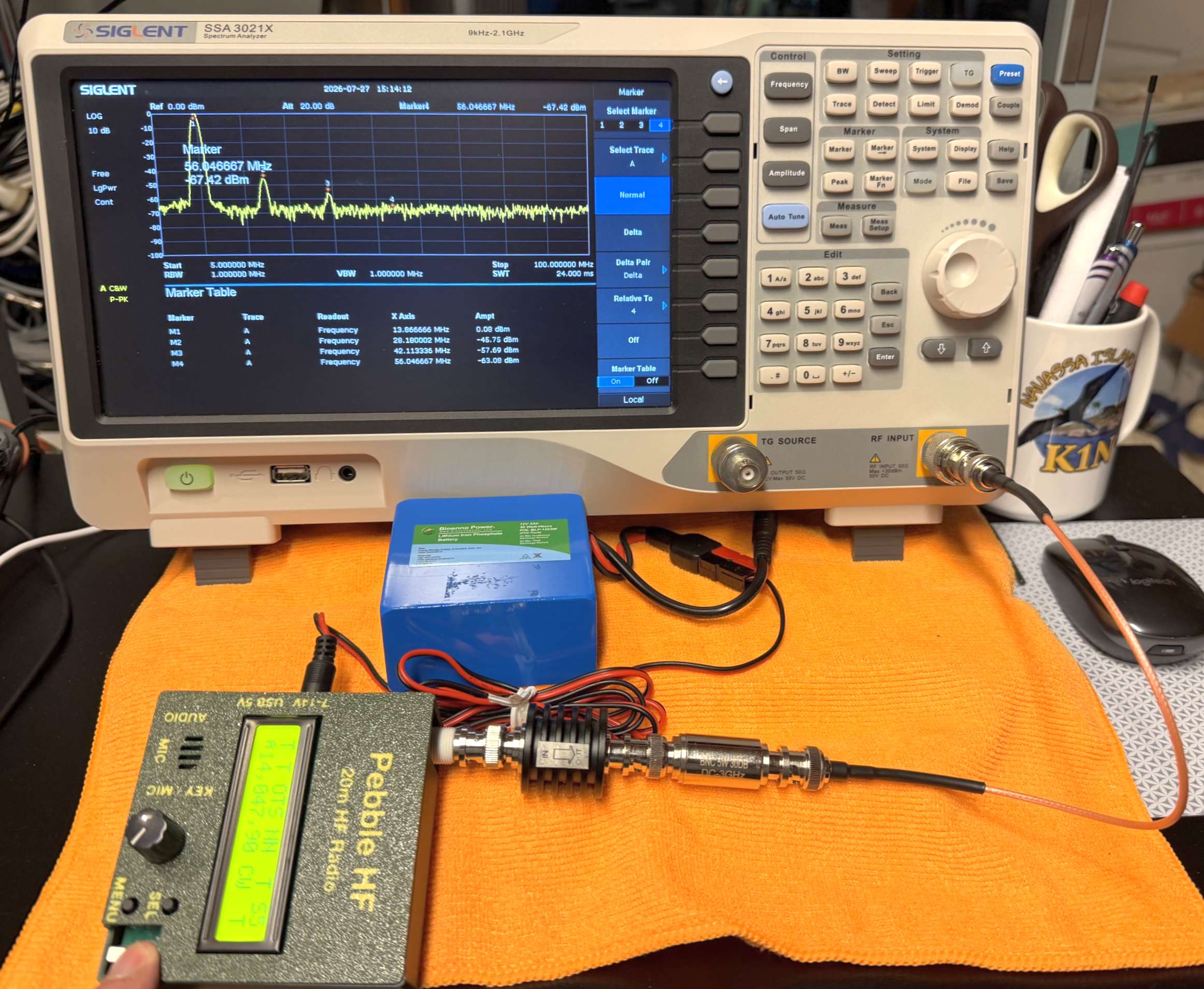
My Pebble puts out close to 6 watts at 14 volts, so the first task was to pick a set of attenuators that would put its output well below the 30 dBm input limit of the analyzer.  I started with a 6dB attenuator rated at 10 watts, then added in another 30dB attenuator rated at 5 watts.  That was a total attenuation of 36 dB.  I then verified that this was the actual attenuation by using the Tracking generator –  sure  enough the attenuators were up to spec.

Next up it was time to check out the harmonics.  I set the analyzer to start at 5 MHz and go up to 50 MHz (enough to catch the 2nd, 3rd, ant 4th harmonic of 14 MHz).  The Pebble fed the 36 dB attenuator, which was connected into the analyzer RF input.  The built-in straight key made it easy to generate the carrier.

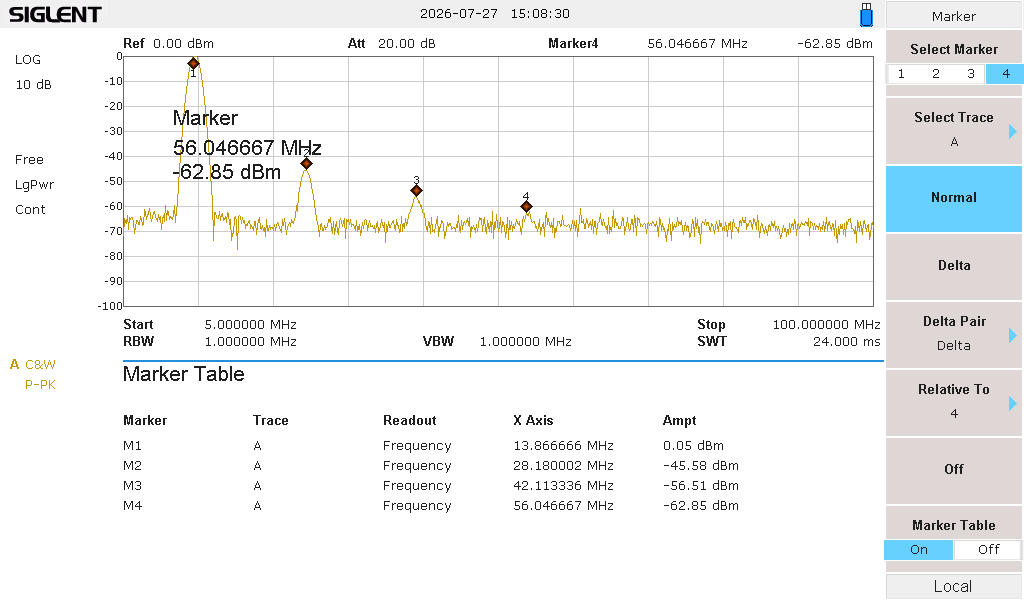
Next I set four markers for the primary and harmonics.  This is what the analyzer reported:

The table shows the 14 MHz carrier was at 0 dB, then the second harmonic was -45.6 dB below that.  The  3rd harmonic was -56.5 dB and the 4th harmonic was at -62 dB.

FCC rule 97.307(d) says “For transmitters installed after January 1, 2003, the mean power of any spurious emission from a station transmitter or external RF power amplifier transmitting on a frequency below 30 MHz must be at least 43 dB below the mean power of the fundamental emission.”

The Pebble passes at -45.6 dB.

Posted in Emissions, Pebble | Leave a comment

A Digital Activation at Fort Wetherill

My club, Newport County Radio Club, has a fairly active POTA group which gets together a couple of times a quarter for activations.  Its a good time to see other rigs, antennas, and simply have a fine time together.


Yesterday, Saturday July 18th, we got together at 10:30 AM at park US-2875.  So far, 5 of us have posted logs, but a few more were there.  Two of us, myself and KK6IK, decided to run QRP.  Scott use a 17′ ground mounted vertical with radials and his KX2.  I used my IC-705 on FT4/FT8 with a Hamstick mag mounted to the top of my SUV.

The east coast was blanketed with smoke from the Ontario wildfires, and the AQI was in the unhealthy range.  It was also hot and humid, so I decided to stay in my car, and run the AC (My RAV4 Prime uses a heat-pump for cooling and creates zero RFI just running off the traction battery.  It uses about 9 watt-hours a minute, so my entire activation consumed less than 0.6 KWH of my 18 KWH battery capacity.)

I initially tried to run the 705 at 10 watts, but my tablet computer immediately shut down.  I dialed the p0wer back to 5 watts and I had no further problems.  I did have a half-dozen large ferrite beads on my feedline as well as about six turns of coax, and I was using a resonant Hamstick antenna, so I was somewhat surprised to have issues.  Next time I will use an actual current choke and be sure to have more ferrite beads on all the cables into the 705.

I had purchased a Fusion5 Helios 12″ Windows 11 Tablet PC to ensure I had no issues with drivers or running software.  It works fine, but is somewhat challenging due to the smallish screen size – it can be difficult for one with shaky fingers to tap the correct spot.  The other drawback is the tablet will only run for about 4 hours on a charge.  Other Windows 11 tablets are based on ARM processors and have issues with a lack of driver support because of that.

I was parked by one of the many coves that surround Ft. Wetherill. This one in particular is popular with SCUBA folks.

My first contact was a P2P at 11:08 AM.  By 12:11 PM I had 12 contacts in the log, six on 20-meter FT4 and six on FT8.  About half the contacts were P2P.

As you can see, most of the contacts were within a single hop from Rhode Island.  At 5 watts I wasn’t busting pileups, and took about 4 times the amount of time I would have required had I been running CW, but it was more about being there and trying digital modes than anything else.

When I uploaded my log, I discovered that the July 18/19 was a “Support Your Parks Weekend”, so I found this waiting for me.

Posted in Activation, FT4, FT8, HamStick, IC-705, POTA, QRP | 1 Comment

World’s Cheapest QRP Antenna “Tuner”?

With all our antenna experiments, our solid-state transceivers can be pushed to the limit.  This is especially true for many QRP rigs, which don’t have internal antenna tuners, and sometimes even lack SWR protection circuits.  An example of this would be the original QCX transceiver.  If you forgot to attach an antenna, or fed it into some inhospitable load, it would promptly emit magic-smoke as the final amplifier bid you farewell.

Things improved a bit when SWR detection circuits were put in to QRP rigs.  The good news was the finals were protected.  The bad news was they often shut down the transmitter completely, requiring a power-cycle to restore operation.  This meant that external antenna tuners couldn’t be used as there was no RF to drive them.

There is a very simple solution to these issues, and some QRP tuners have implemented it in the form of a TUNE vs. OPERATE switch.  The tuner simply switches in an attenuator when in the TUNE position.  The output end of the attenuator still provides enough power to allow the tuner to be adjusted.

A 6dB attenuator guarantees that the worst case SWR seen by the transmitter is no more than 1.67:1, well under the 2:1 range that starts to cause transmitter issues.  Short the output of the attenuator, or leave it open, and the SWR will never exceed 1.67:1.

Since a 5 watt  QRP rig will still produce more than a watt of power at the output of the attenuator, one could use a 6dB attenuator with ANY antenna.  That might be ideal for use with a multiband WSPR transmitter – allowing instantaneous band changes.

An example of such an attenuator, rated at 5 watts and costing about $15, is shown below

Posted in QRP | 1 Comment