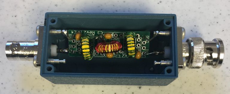
A friend of mine, Paul K1YBE, gave me a QRP Labs 40-meter Low Pass Filter Kit. The kit came with three T37-6 cores, some #28 wire, 4 caps, a tiny PCB, and a couple of headers. Normally used with one of their WSPR Transmitter Kits.
The filter was easy to build, but I found the inductors needed to have a turn removed to yield their desired value. This equated to 20 turns of #26 wire for L1 and L3 (1.37 uH Q17), and 23 turns for L2 (1.81 uH Q15). The caps had a measured tolerance of +/- 3.5%. The 270 pF caps had a Q of 30, and the 680 pF caps had a Q of 260 (all Q values at 100 KHz).
Assembly was straight forward, and I used my Quad-Hands to help keep things steady while soldering – especially the flying leads I was going to use to mount the filter in the box.
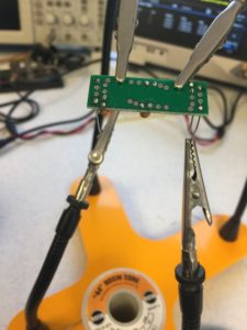
I mounted the assembled PCB into a Pamona 2391 BNC box. This is a great solution because the box will connect directly to the Pixie output using a Male BNC, and provides a filtered output on the female BNC.
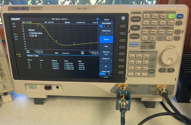
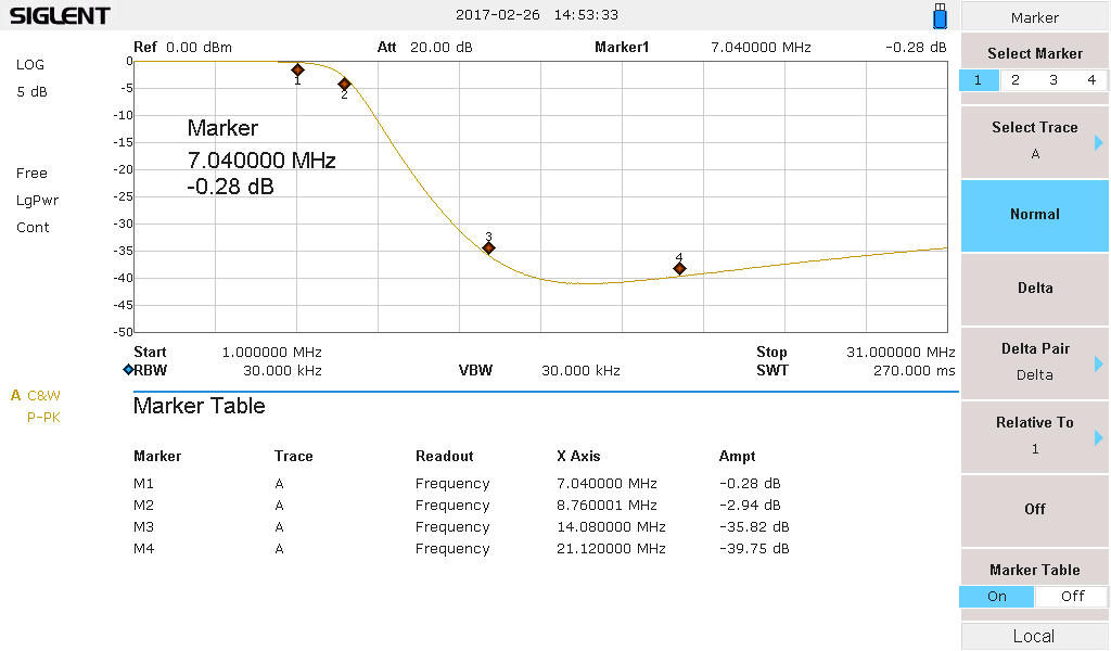
The filter response was swept with my spectrum analyzer. Being a 7-pole design, the loss was much less at 7.040 MHz, only about 0.3 dB down. At 14 MHz the response was down about 36 dB, and 39 dB at 21 MHz. In truth, had I not removed a turn for the two inductors, the 3 dB point (8.76 MHz) would have shifted a bit lower, probably providing a tad more rejection at 14 MHz. Given the tiny box it was easy to hook the filter to the SA.
The real test was hooking the filter to the output of the Pixie.
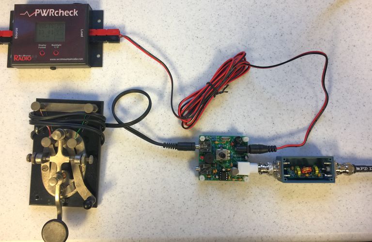
Looking at the output on the SA was pretty gratifying:
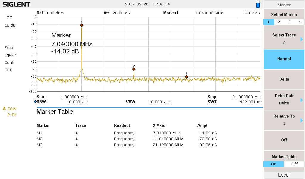
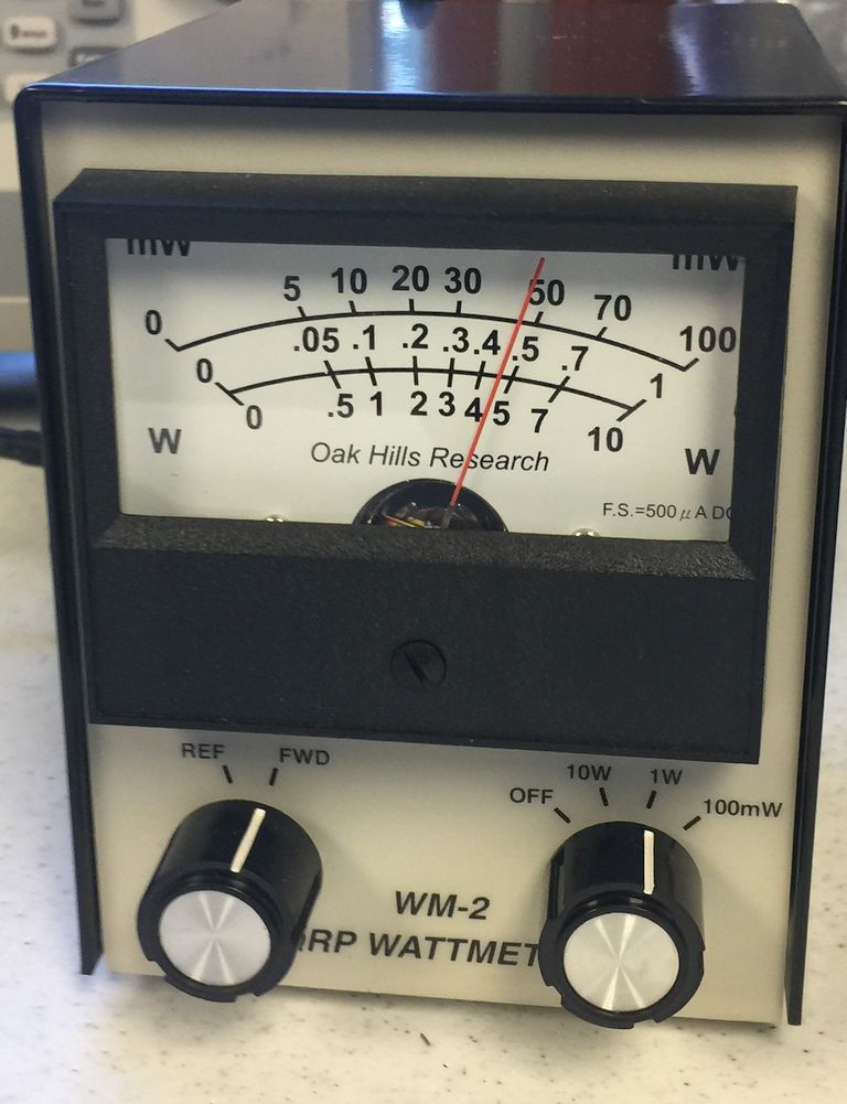
The 2nd harmonic is down 59 dB and the 3rd is down 69 dB from the carrier. The SA shows 26 dBm output (400 mW). The power meter shows 450 mW (these tests were run using a 2N2219 for Q2).