
As I mentioned the 40-meter Pixie QRP rig has pretty horrible harmonics, well above the maximum allowable FCC limit (-43 dBc). One Pixie was about -9 dBc, and the other was about -20 dBc.
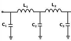
The output filter in the Pixie is a simple 3-pole PI network, clearly not up to snuff. With judicial parts placement, an extra 5-pole filter could be installed, but it probably makes sense to install it in an external box (Like a Pomona 3231 or 2391).
Several club members and I embarked on experiments to build a prototype filter, with some different choices of -3 dB cutoff frequency, output ripple, etc. We also discovered that while many of the online calculators produced very similar results, at least one of them does not. Filters built using those values did not match up well with predicted results.
John King, WA1ABI, suggested using “Elsie” from Tonne Software. Far more flexible than the online calculators, it produced output values that were consistent as long as the initial parameters were correctly selected. The software can be downloaded here:
http://www.tonnesoftware.com/elsiedownload.html
I used an online calculator that produced identical results to Elsie:
http://www.calculatoredge.com/electronics/ch%20pi%20low%20pass.htm
Input values were a cutoff frequency of 7.5 MHz, 50 Ohm impedance, 1 dB ripple, and a 5-pole Chebyshev filter. That produced the C1/C2/C3 & L1/L2 values shown below:
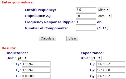
C1 & C3 were fabricated from a 680 pF in parallel with a 220 pF, for a total of 900 pF (less than 1% low).
C2 was fabricated from three caps in parallel; 470 pF, 470 pF, and 330 pF, for a total of 1270 pF (less than 1% low).
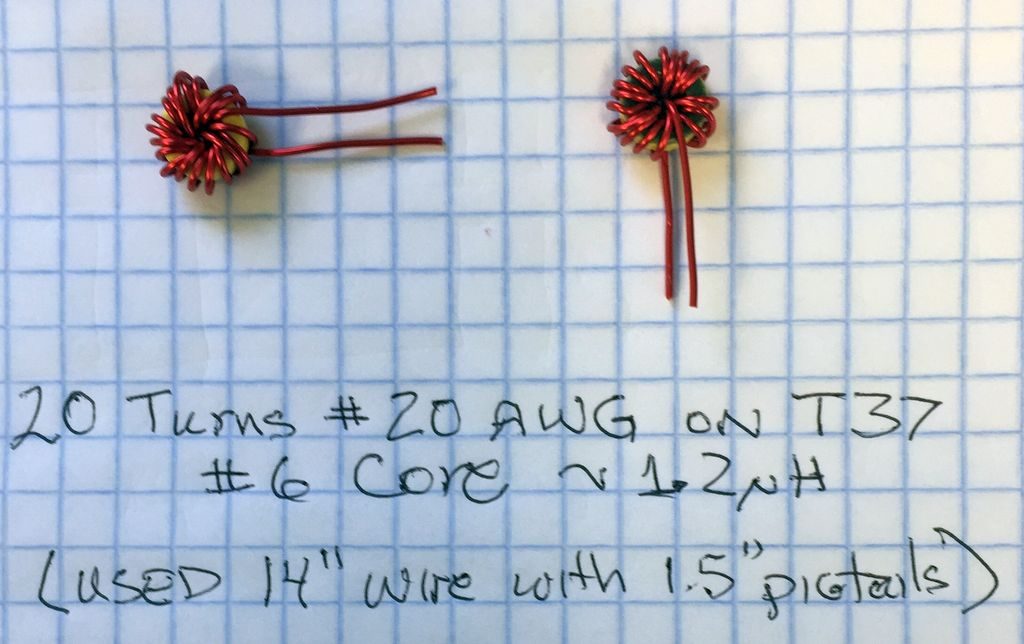
My inductor was set to 1.2 uH, about 4% high, but that required 20 turns on a #6 core.
I had chosen T37 cores for their small size and had initially planned on winding them with #26 wire. However I switched to #20 for mechanical reasons. A T37 core can hold about 13 turns of #20 in a single layer, and 20 turns of #20 in a dual layer — perfect. 14″ of #20 magnet wire was enough to wind 20 turns with 1.5″ long pigtails. It was tight, but things fit.
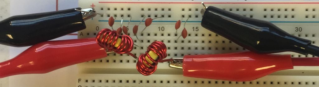
The final breadboard circuit looked like this:
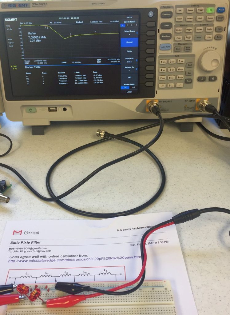
The test setup looked like this, with the breadboard hooked up in series between the Tracking Generator output and Spectrum Analyzer input:
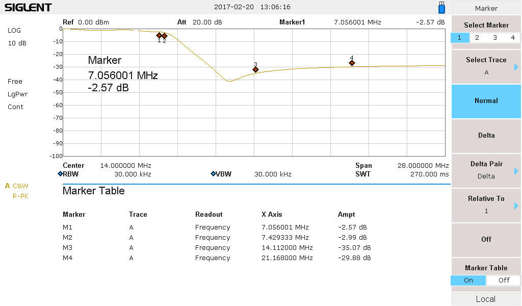
The measured response was:
- 7.055 MHz -2.6 dB (Operating Frequency — loss is higher than expected)
- 7.429 MHz -3.0 dB (Cutoff Frequency — a bit lower than expected)
- 14.112 MHz -35.1 dB (2nd Harmonic)
- 21.168 MHz -29.7 dB (3rd Harmonic)


Pingback: Pixie with 5-pole Axial Filter Passes | WB4SON
Very nice work. Five years later, I am trying to do the same thing, only with zero background in electronics.